1948 Velocette Mac
1948 Velocette Mac
Will keep me from being bored I guess!!!
A brief statement of the Velocette M Series is given below
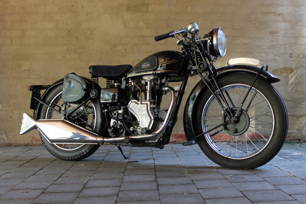
Velocette MAC

1936 Velocette MAC Sport
In 1933, the company decided to introduce a new line of overhead valve (OHV) machines, in order to cut production costs and make a more affordable motorcycle. The K series was expensive to produce, requiring selective hand assembly of the shaft-and-bevel camshaft drive; it was determined that a simpler OHV design would be quicker to build and require less skilled labour to assemble. The first of these new machines was the MOV, using a 250 cc engine of 'square' dimensions (68 mm bore and 68 mm stroke). It was an immediate sales success, having lively performance for the time (78 mph or 126 km/h), and proved a reliable machine with excellent road manners. From this machine, by lengthening the stroke of the crankshaft, the Velocette MAC 350 cc was introduced in 1934. It proved even more popular than the MOV, and became a real money spinner for the company, bringing much needed capital into the firm. In 1935 an entirely new machine was introduced, based on the two previous OHV models, the Velocette MSS of 500 cc. A new, heavier frame was utilized with the intention that the machine could serve as a sidecar hauler. This new frame was developed from the mkV KTT racing machine, and was shared with the KSS MKII of 1936–1948. The MSS also proved very popular and profitable for Veloce.[1] A 350 cc version of the MOV was the basis for the company's World War II military motorcycles.[2]
The Beginning
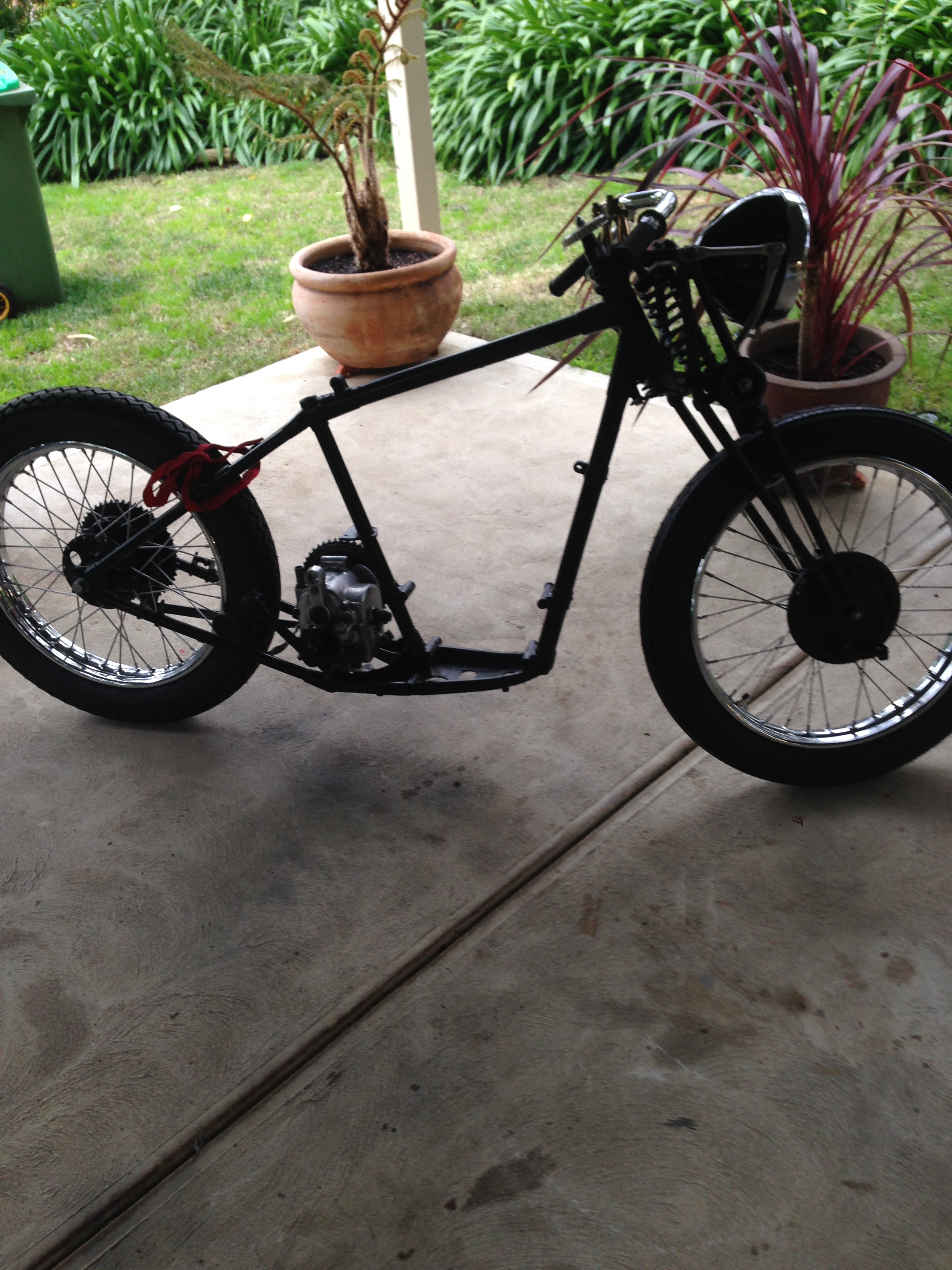
The major challenge and a big one is to restore a 1948 Velocette MAC from the parts that I obtained as shown in photographs below
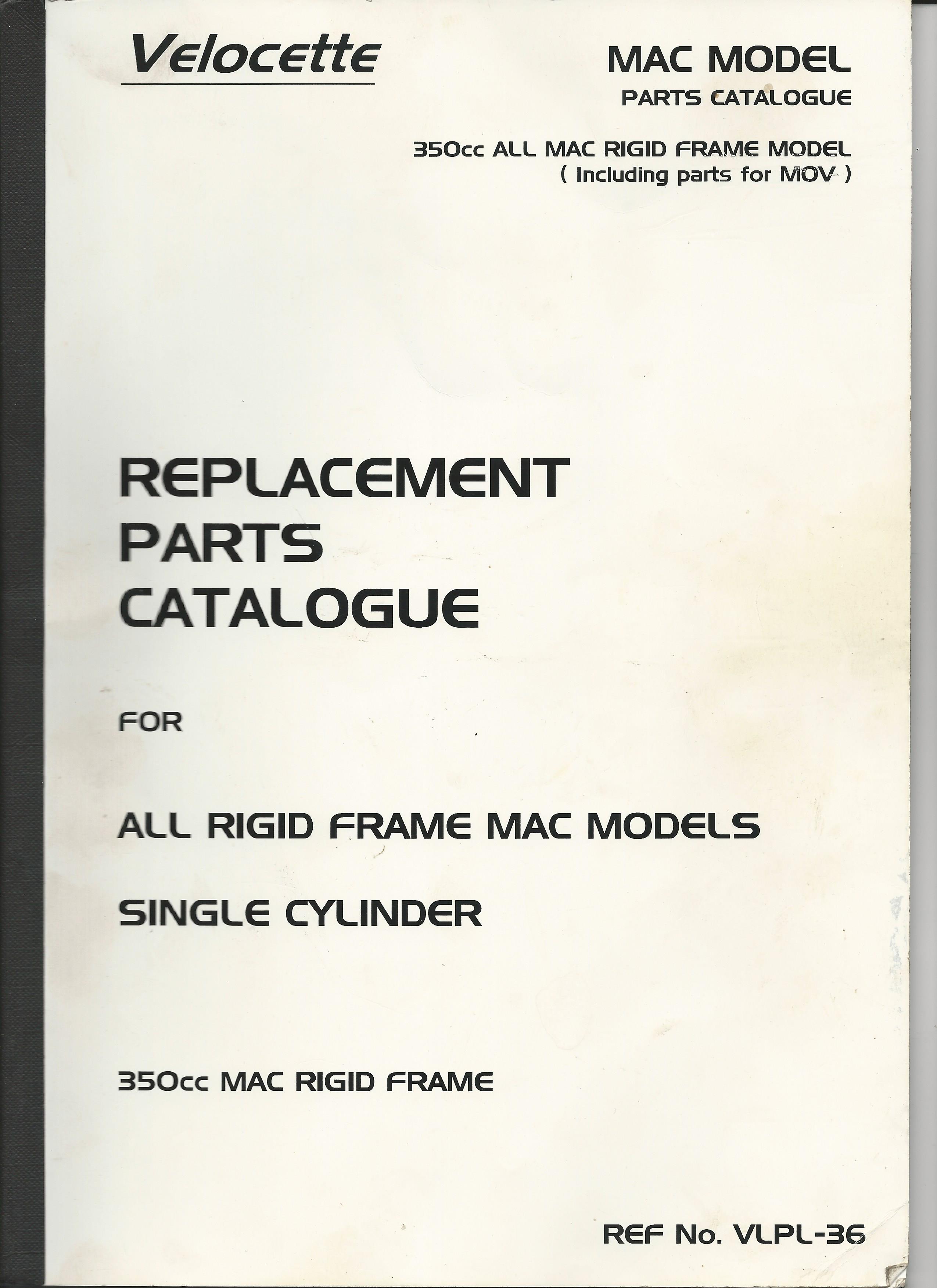
The next step and a very important one was to search and find a parts list for the 1948 Velocette MAC Web searching enabled me to purchase this invaluable parts list
Next I joined the Velocette club which allowed me to access their spare parts and valuable knowledge from club members in particular Norm Trigg
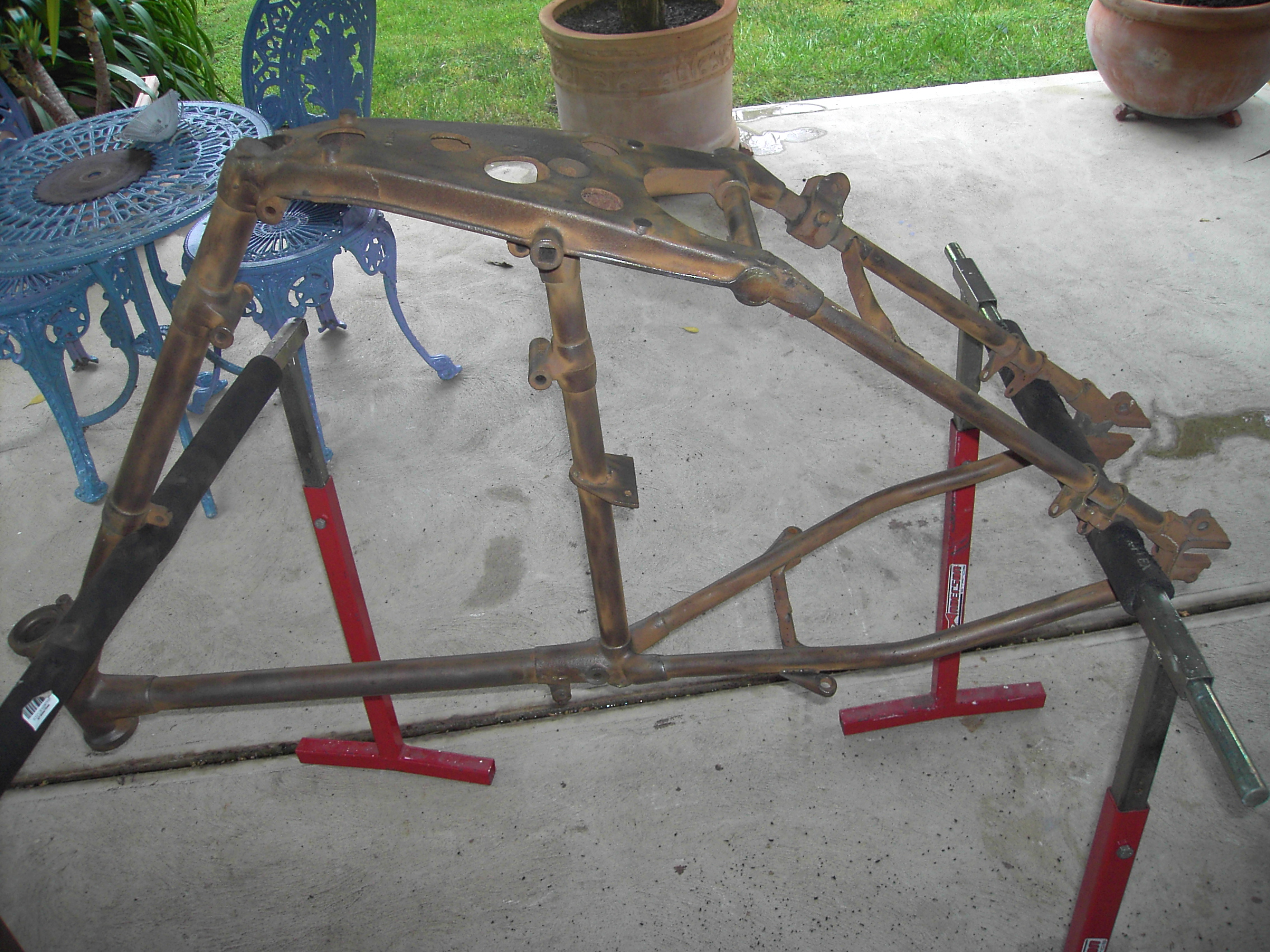
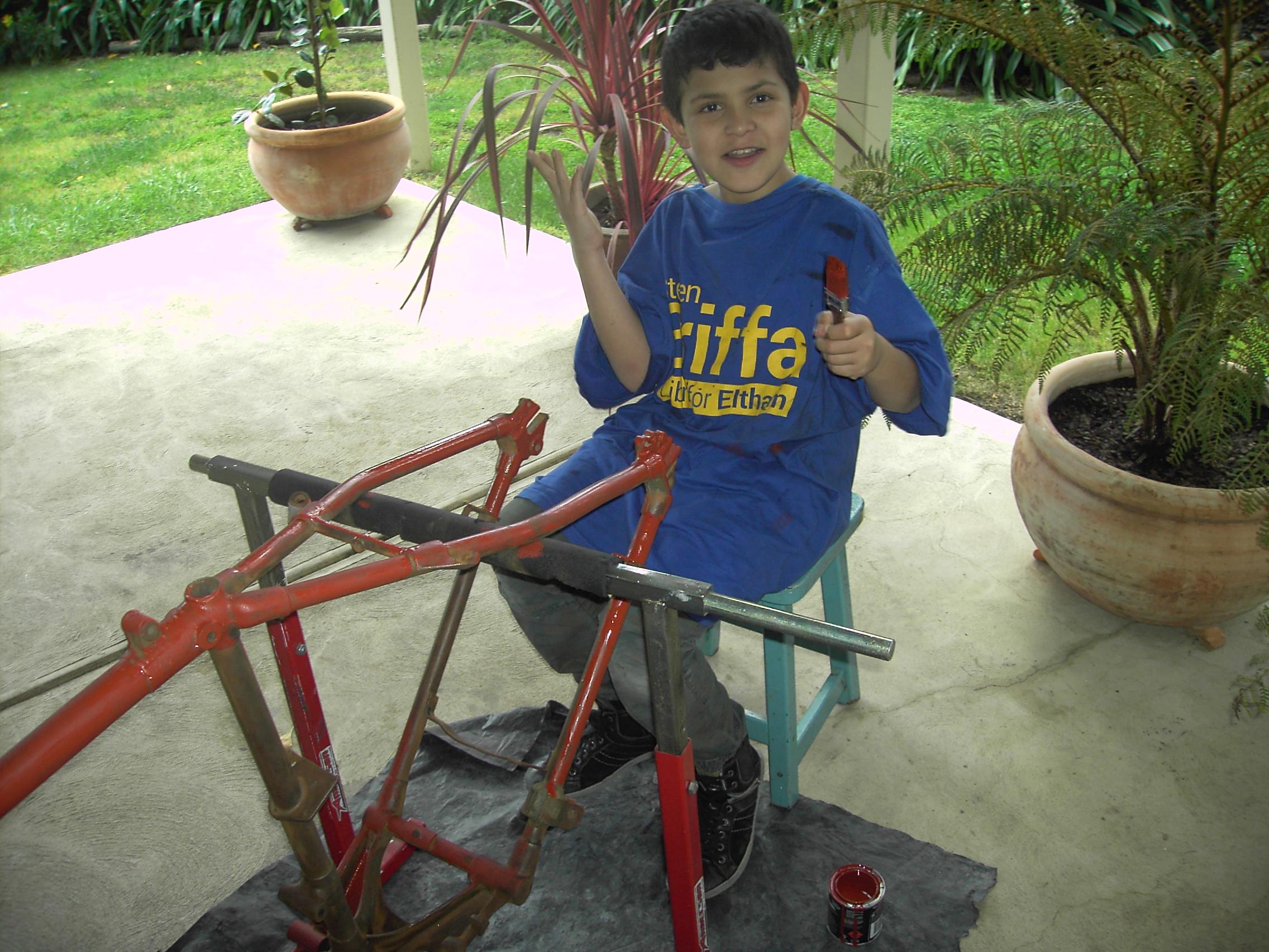
Frame
Decided to commence on cleaning the frame, under-coating with rust proof paint and applying black enamel all with the help of my grandson.
Identified frame number and bike is definitely 1947-48

Decided to powder coat frame and forks as I was not happy with my effort of painting, I would recommend as it is more durable and certainly better than my effort.
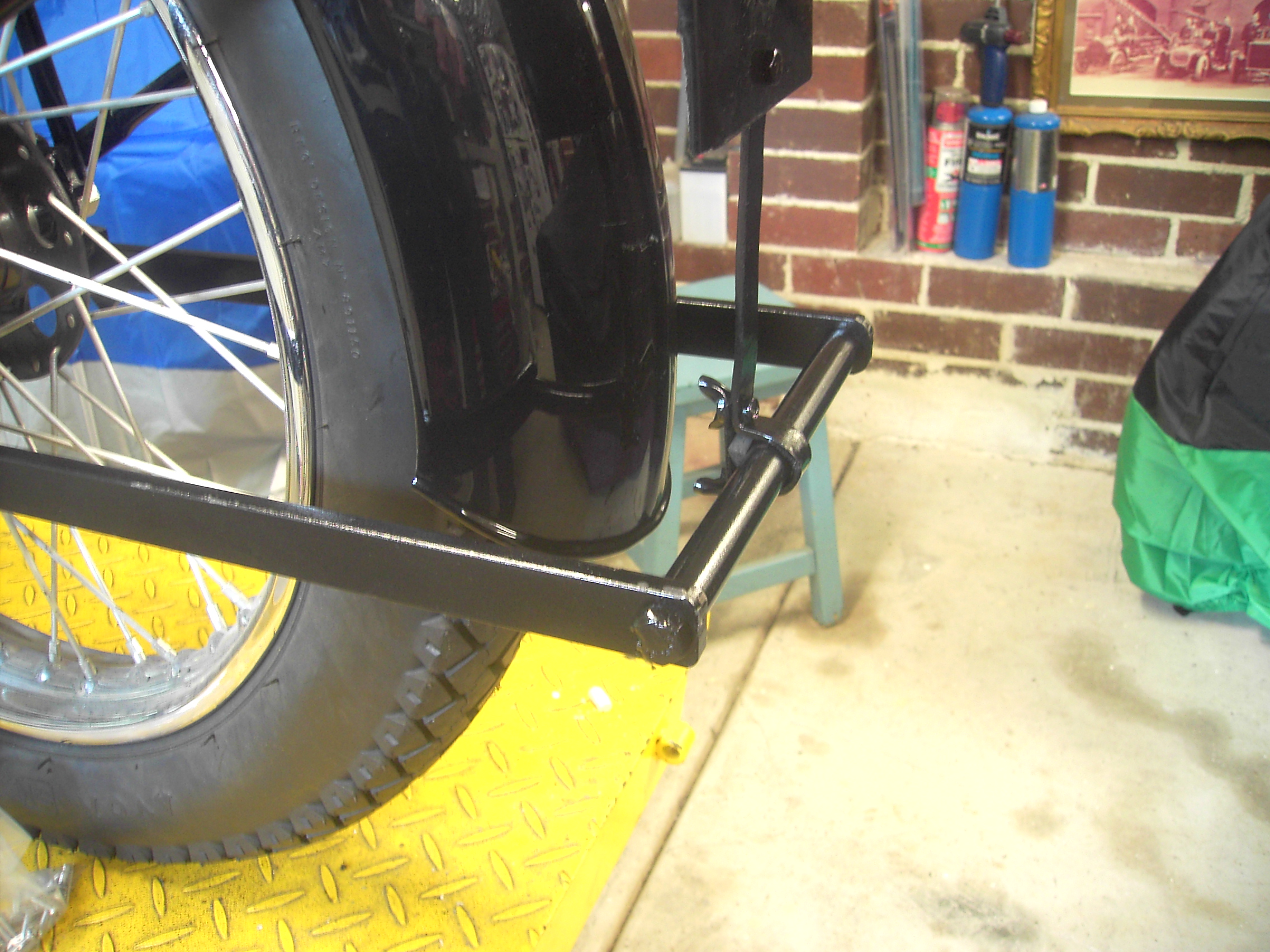
I had great difficulty acquiring a back stand at a price that I was prepared to pay, so manufactured my own.
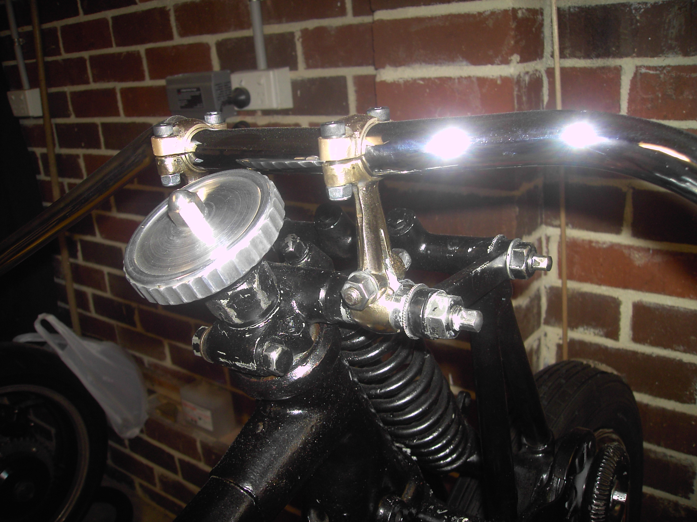
Forks
Located a set of olematic forks on ebay which I purchased. Inspection revealed they would require work and I had always wanted to go with the girder forks which I had purchased with basically no fittings.
[gallery ids="942,944,943" type="rectangular"]
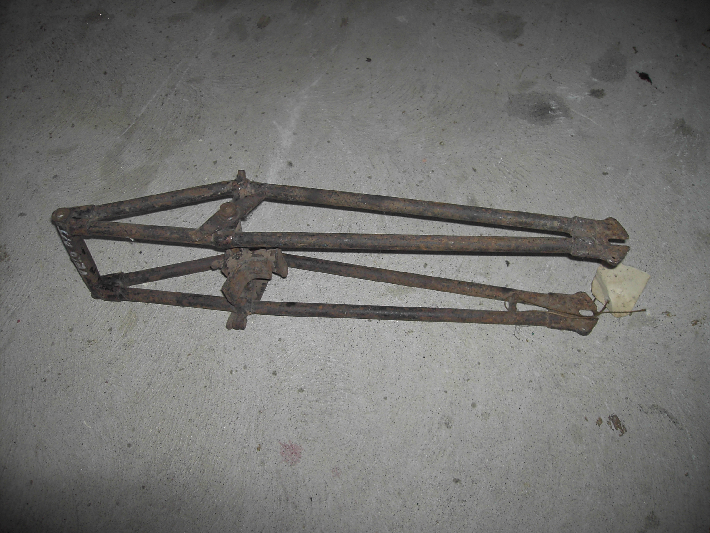
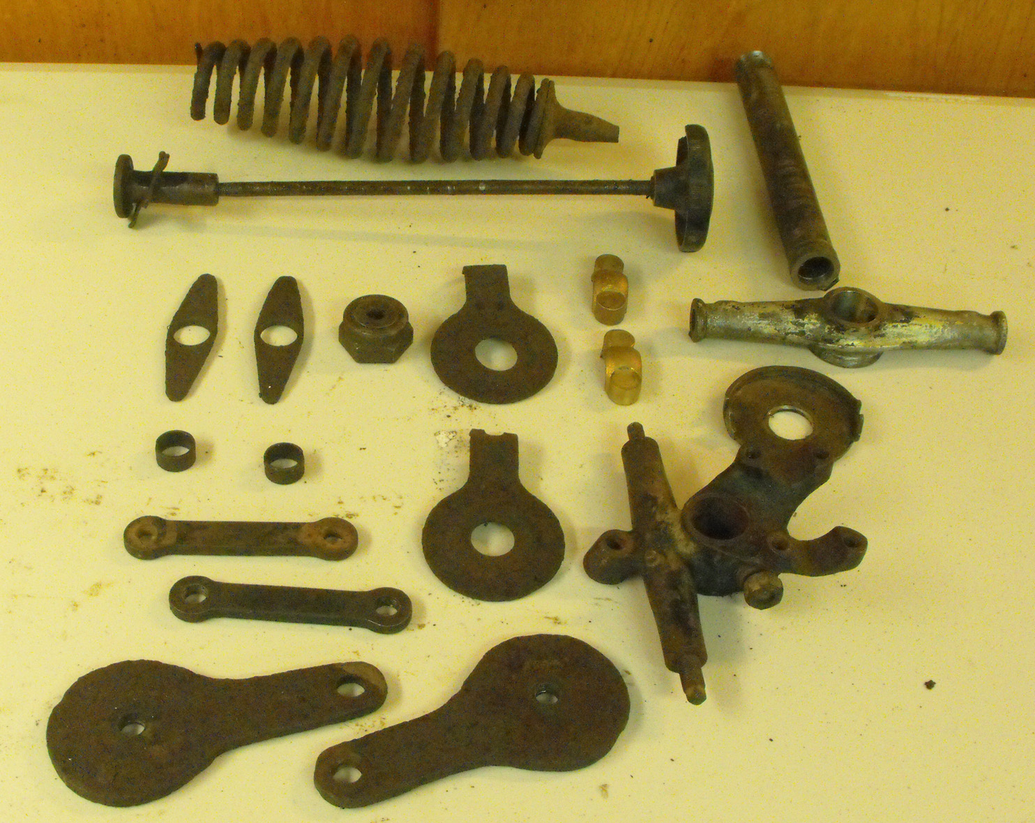
The above photos show fittings for girder forks but further investigation revealed they were not MAC but for the smaller 248cc MOV I am currently following up a lead for MAC girder forks Was successful with girder forks for the Velocette MAC which I thank my friend Norm Trigg
The smaller forks I will keep and use on my next project which is a Francis Barnett
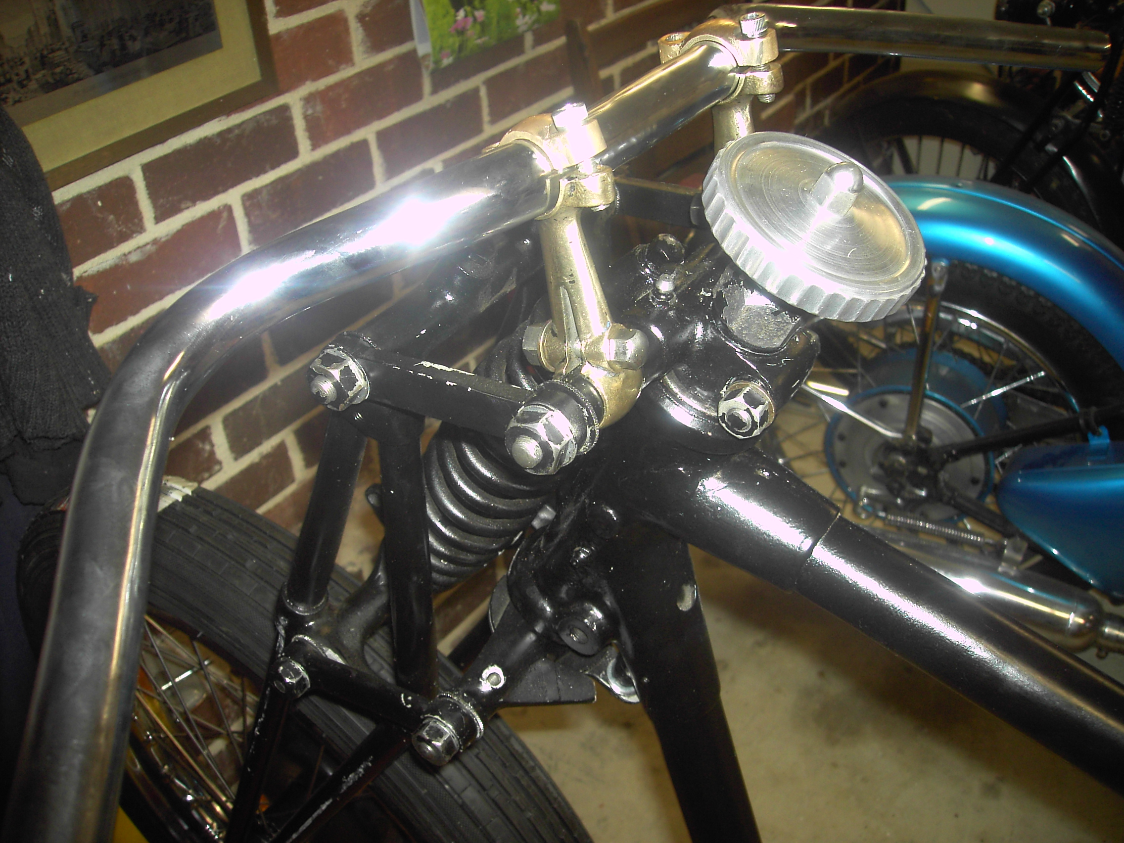
Fitted handlebars and decided not to paint fittings but polish i am happy with the result
Sourced 8 inch headlight and brackets England and South Australia respectively

Tyres were purchased from local supplier Eurobrit and guards sourced from England (Groves)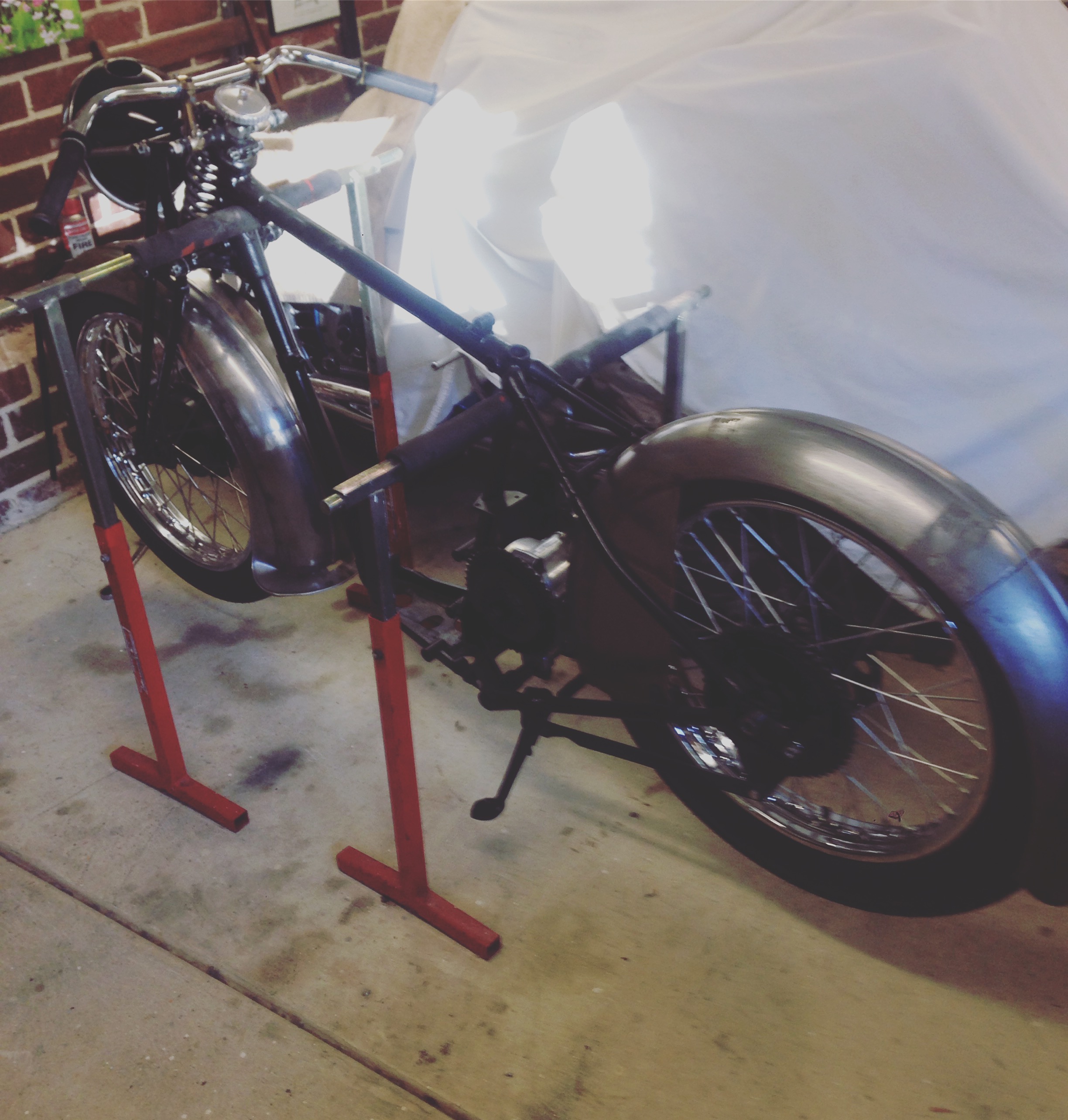
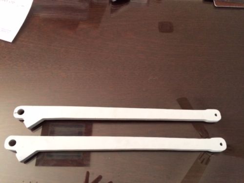
Next to step was that guard brackets had to be manufactured. Lots of patience required.
[gallery ids="1105,1106,1107,1108" type="rectangular"]
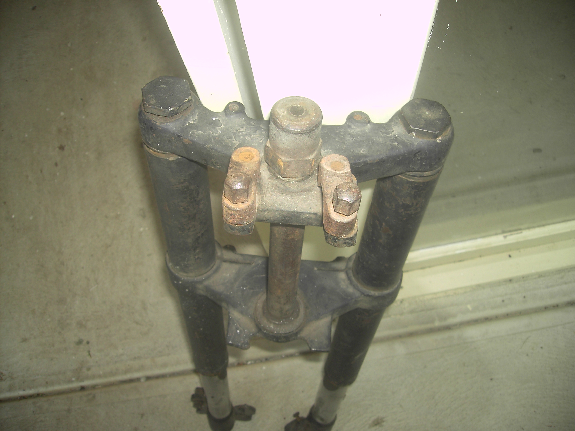
After all this work I decided my painting efforts were not good enough and proceeded to dismantle girder forks, remove gearbox and send away for powder coating which is more durable
Below are the disassembled parts of the girder forks
[gallery ids="1297,1298,1299,1300" type="rectangular"]
I am keen to see the completed powder coated final components
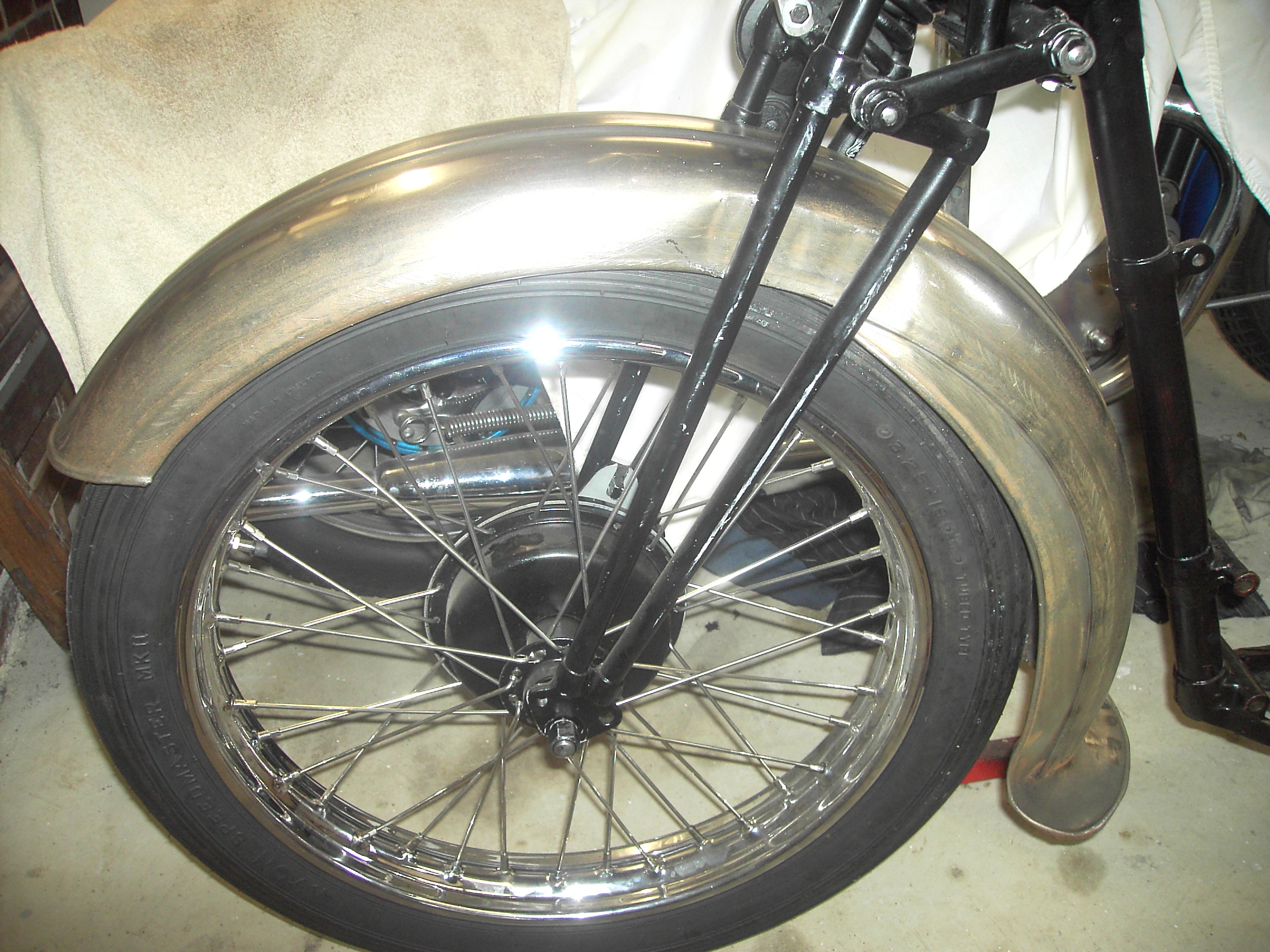
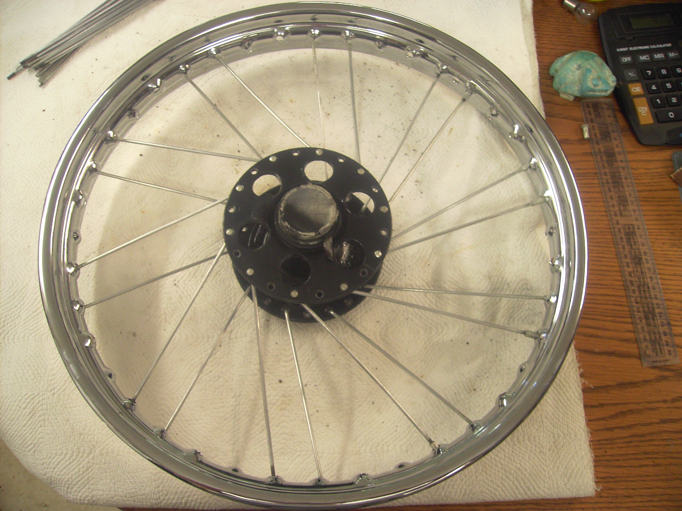
Wheels
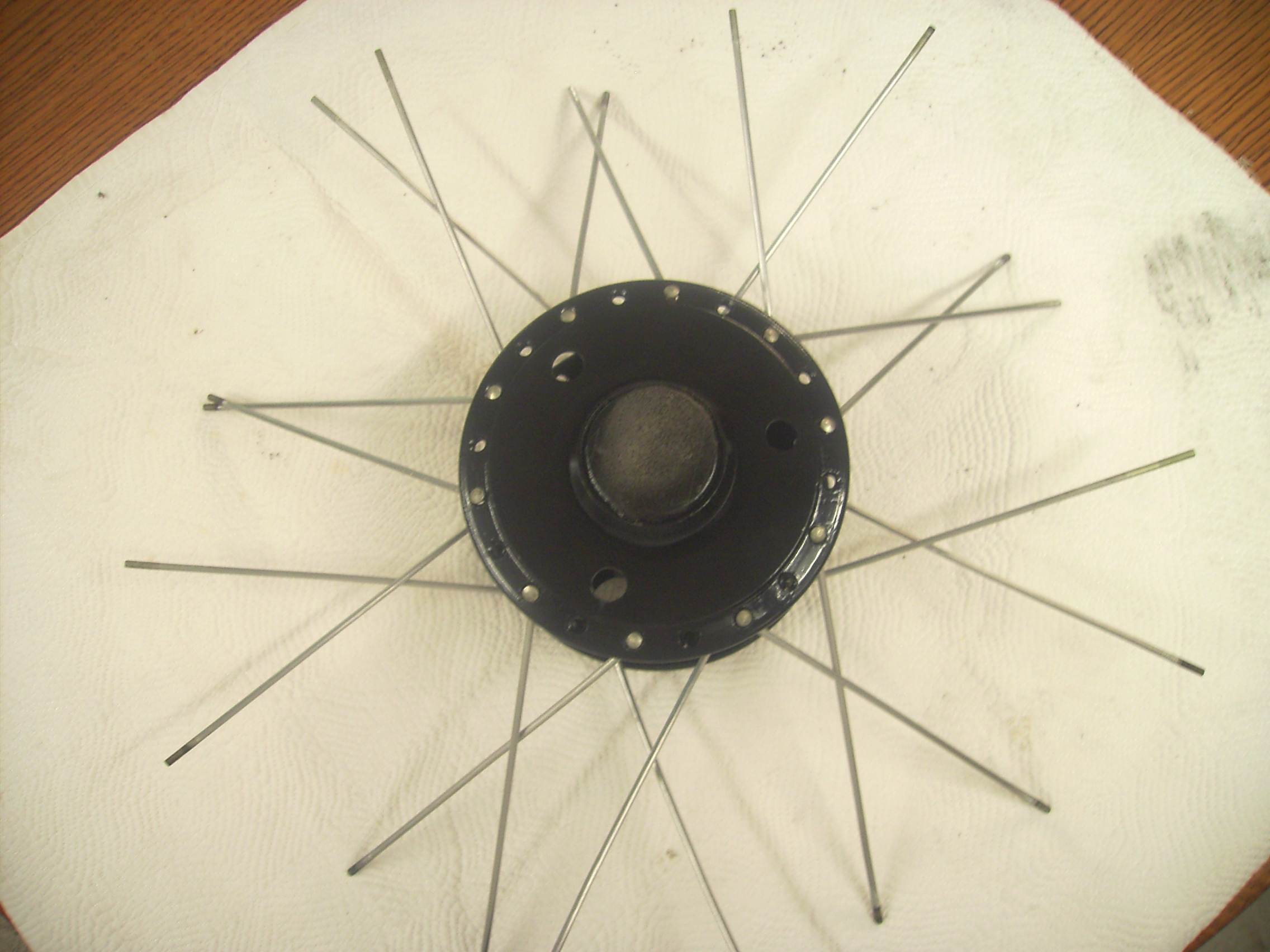
It is worth stating back wheel has 40 spokes and front wheel 36 spokes both with 19 inch rims
Both rims were cleaned up and re-chromed
I decided to re-spoke wheels myself this is a challenging exercise but satisfying
see photos

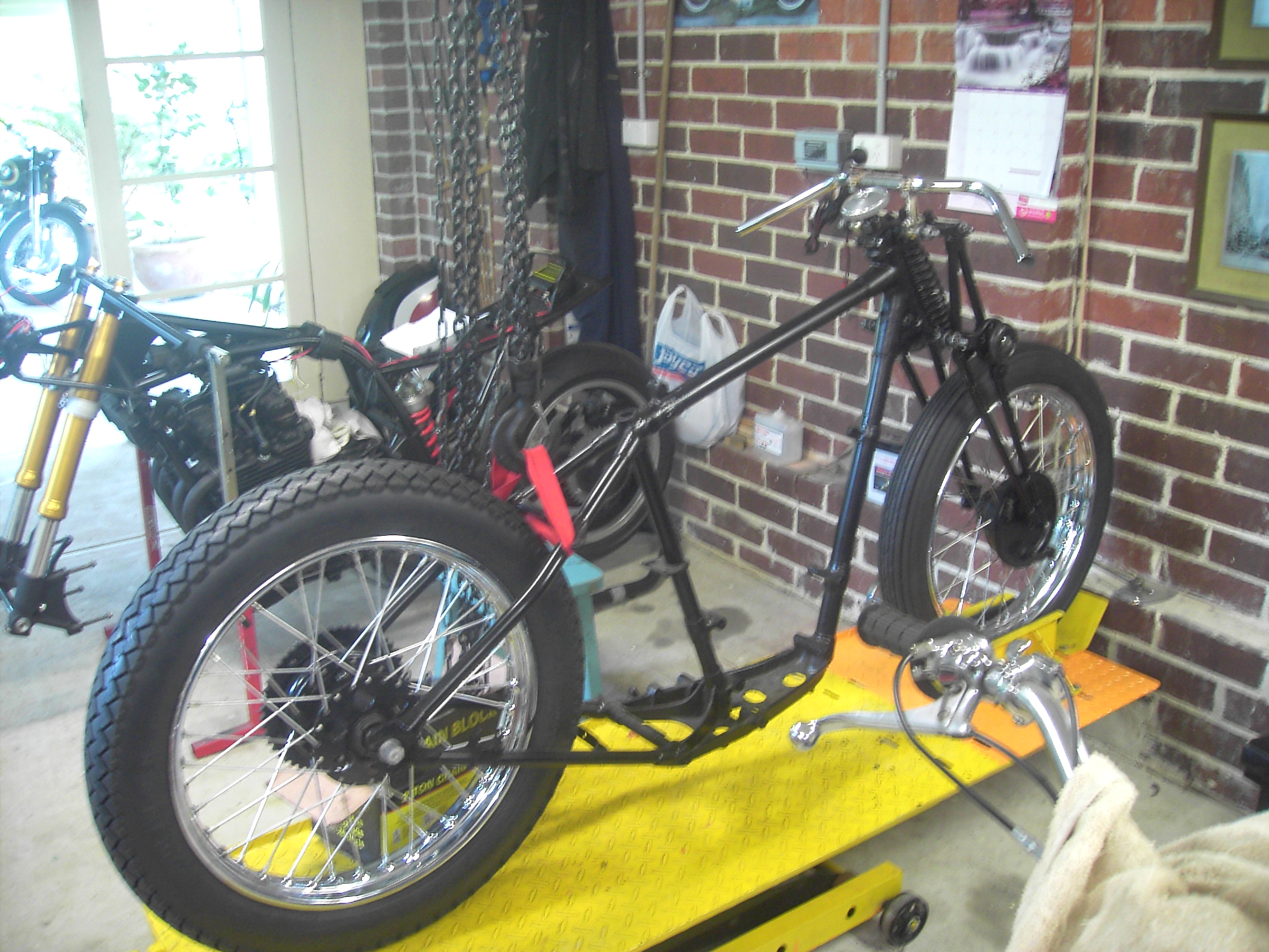
With wheels complete purchased tyres and mounted on frame with my new Webb forks which are now fitted to frame and looking great.

With no mounting plates it was necessary to position engine and gear box casings to establish reference points for mounting plates templates which can then be manufactured
Have purchased brand new guards from Groves (England) and commenced fitting to frame, it has been necessary to make the supporting brackets for both front and rear guards. interesting challenge particularly welding to ensure you don't burn holes in guard.
Could not source a side stand manufactured my own
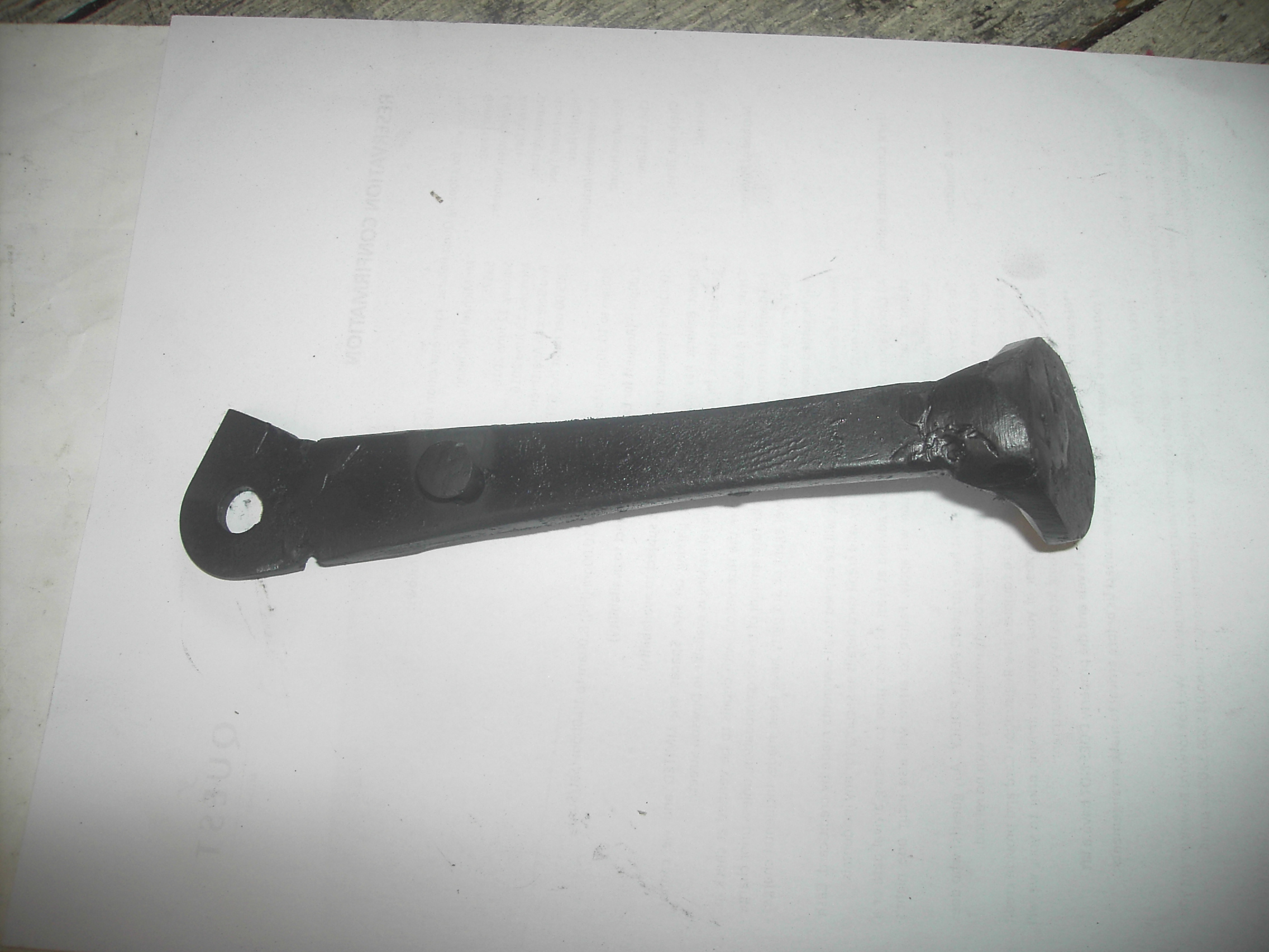
Whilst in the mood also made gear box adjusting chain clevis lever
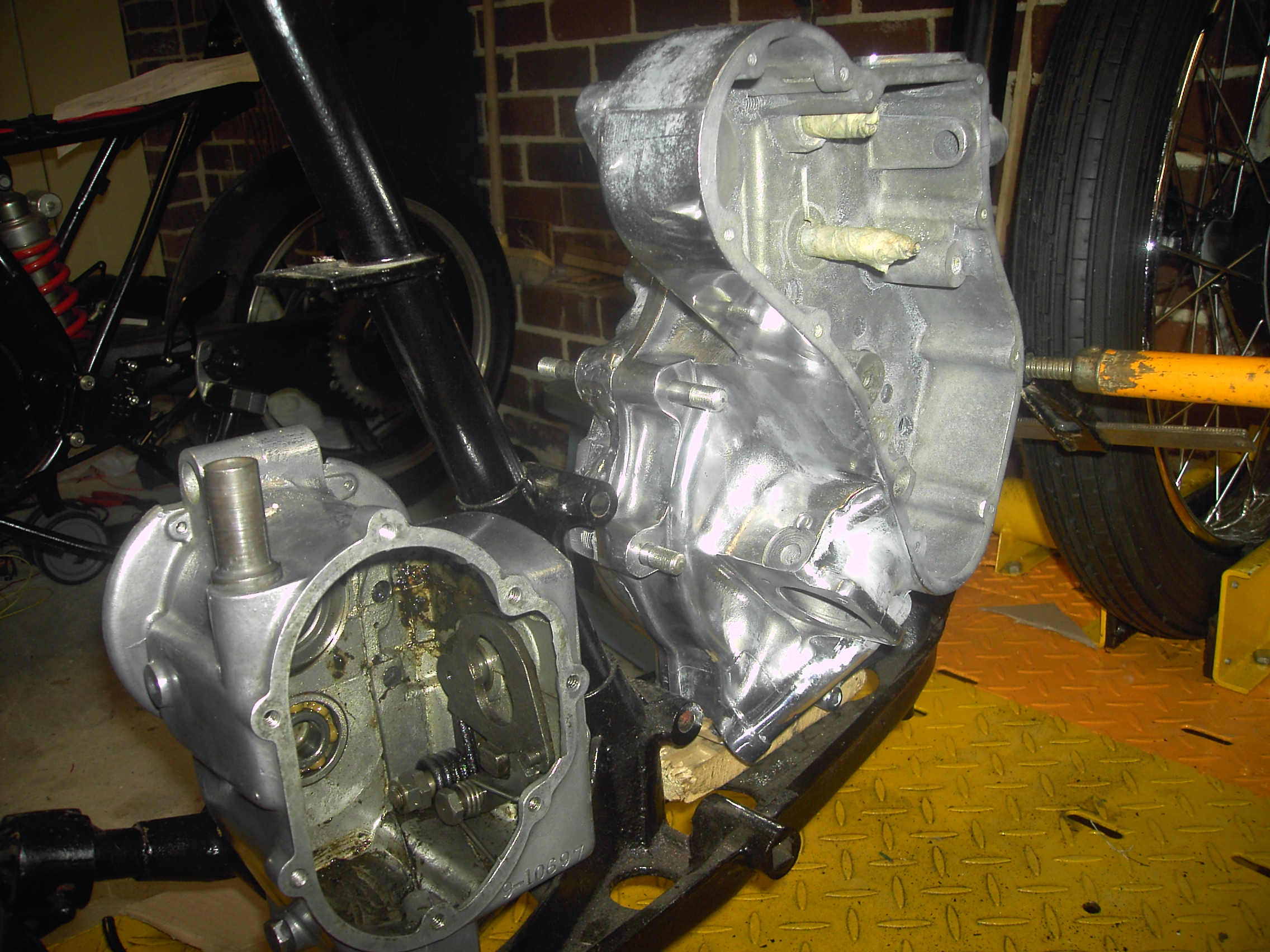
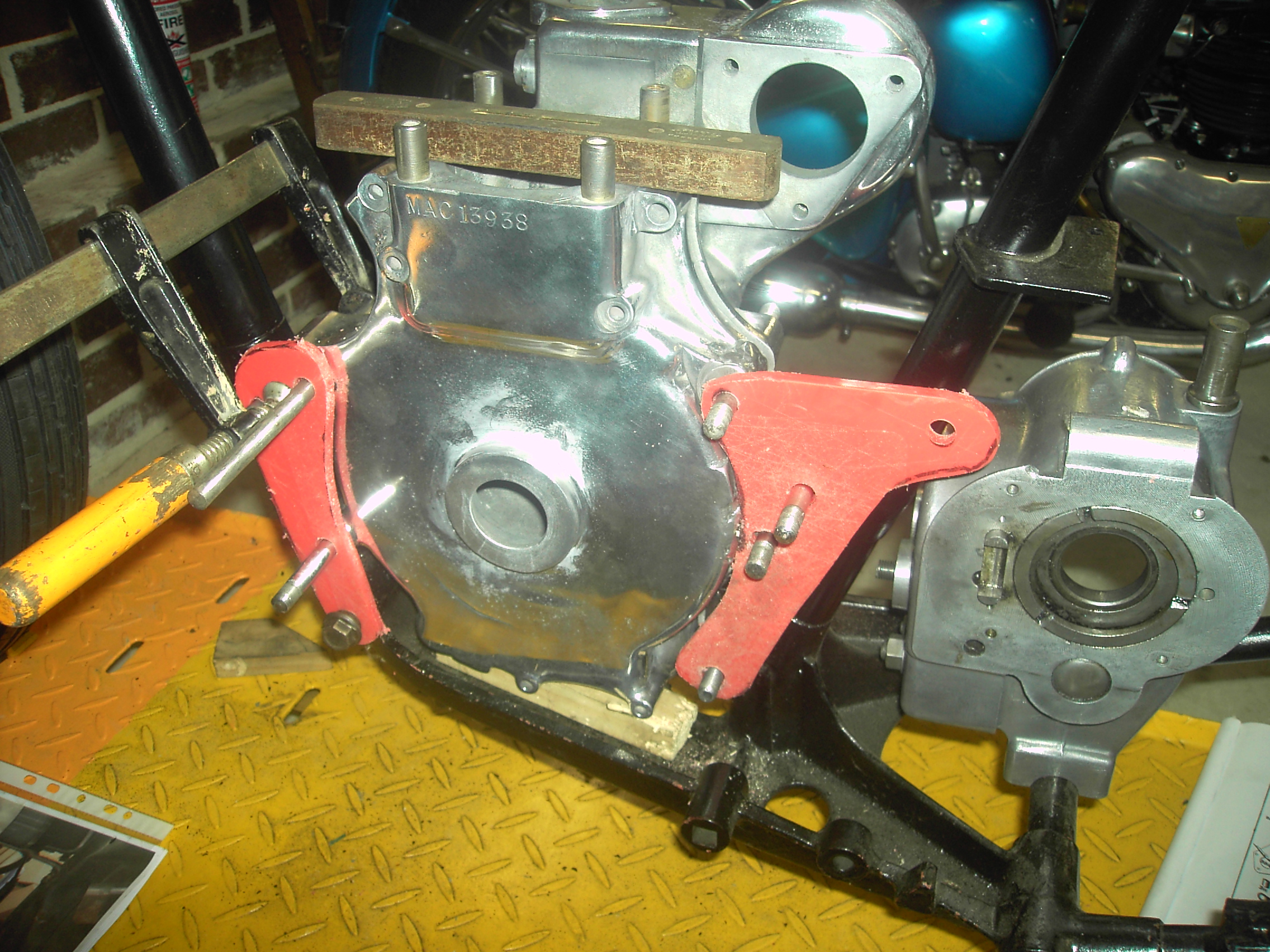
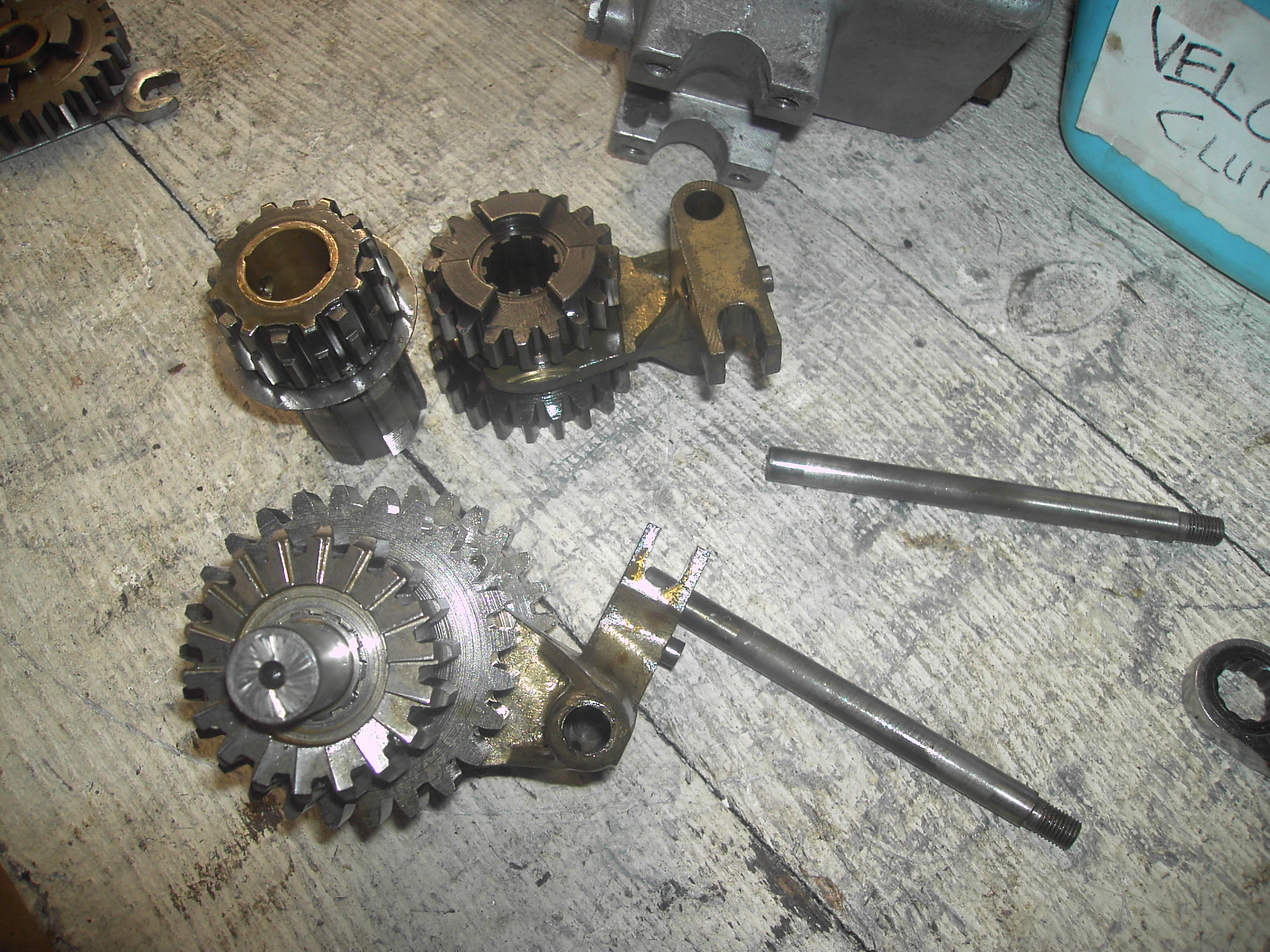
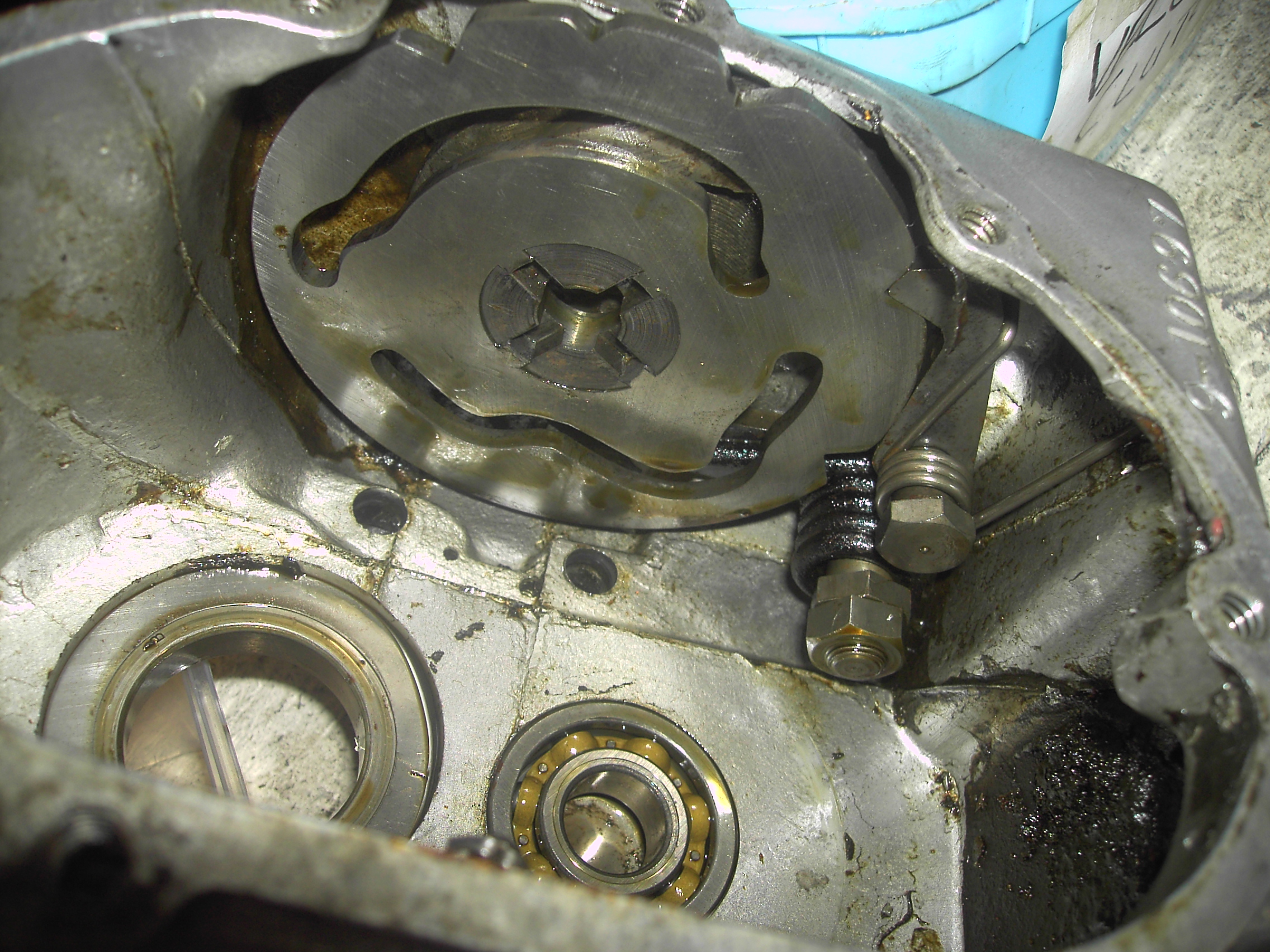
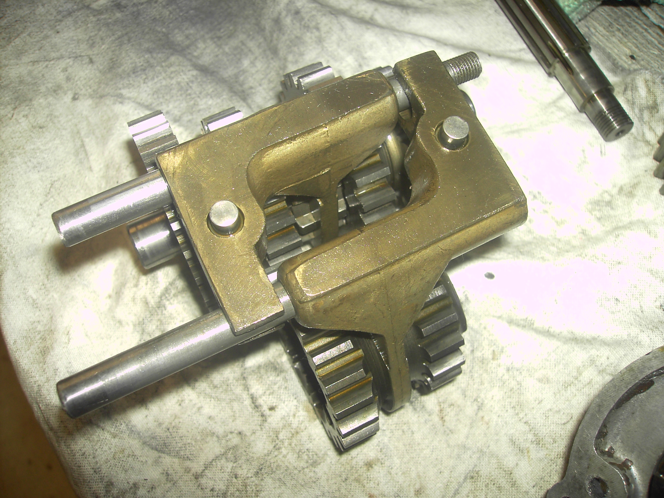
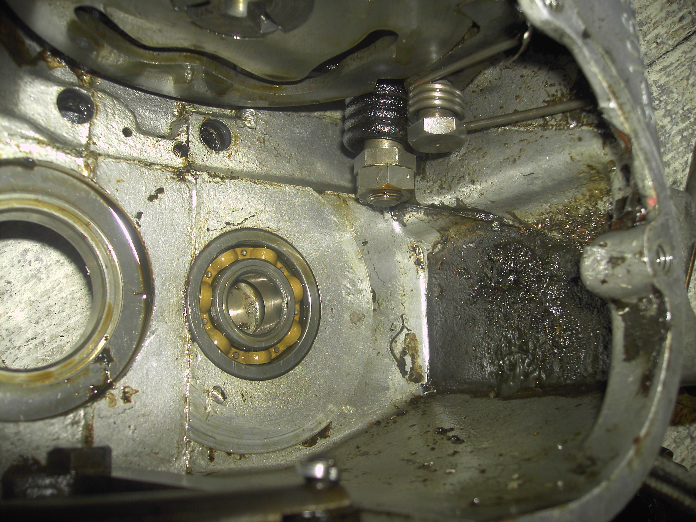
Whilst waiting for the mounting plates to be manufactured in 3mm mild steel plate I decided to commence gearbox overhaul.
After all the work of making templates I have been fortunate to acquire the correct mounting plates
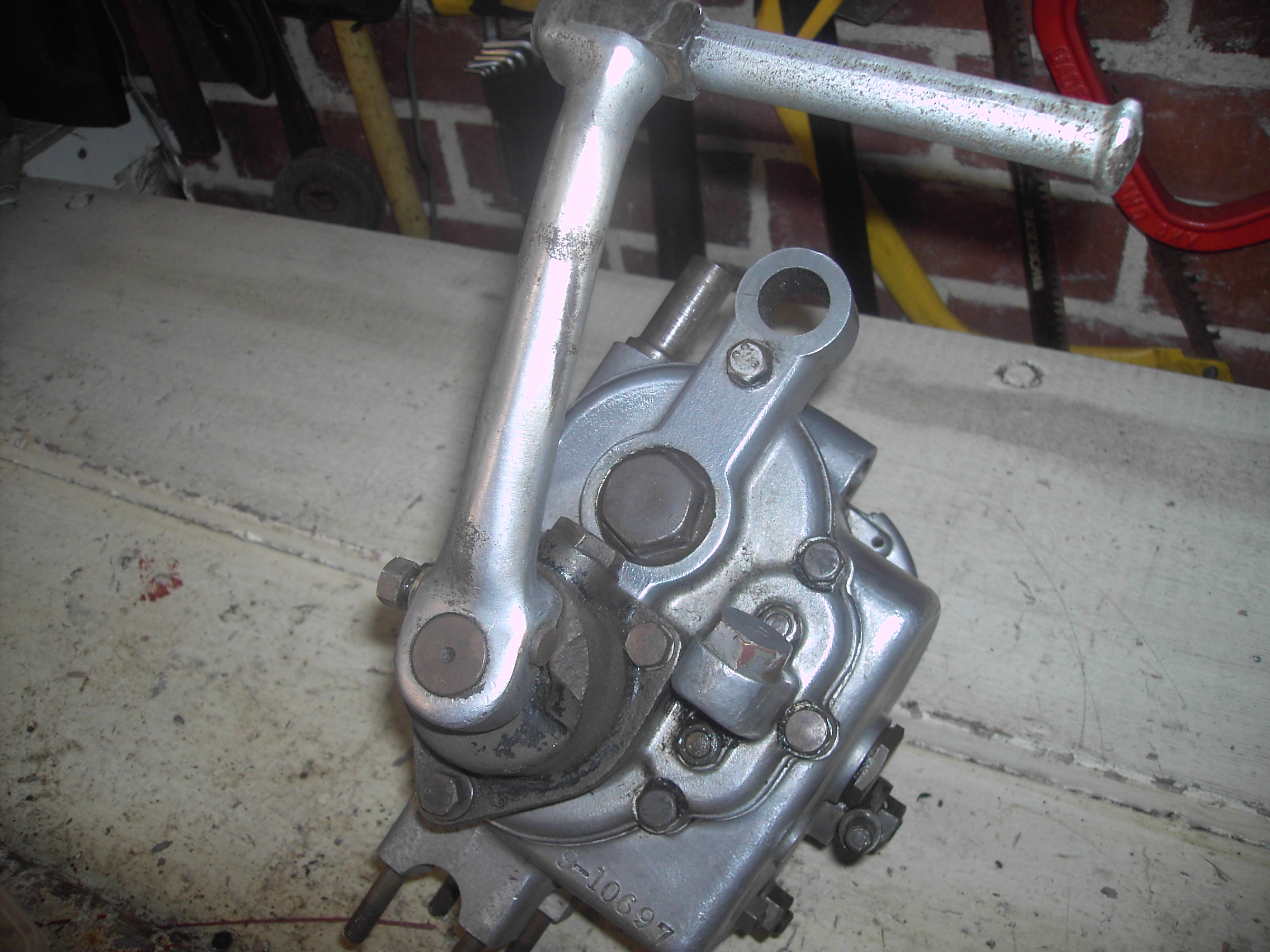
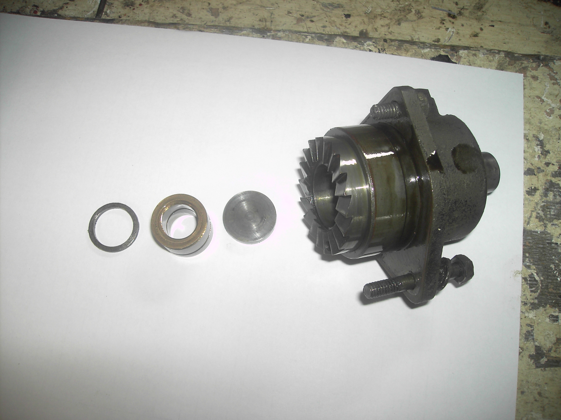
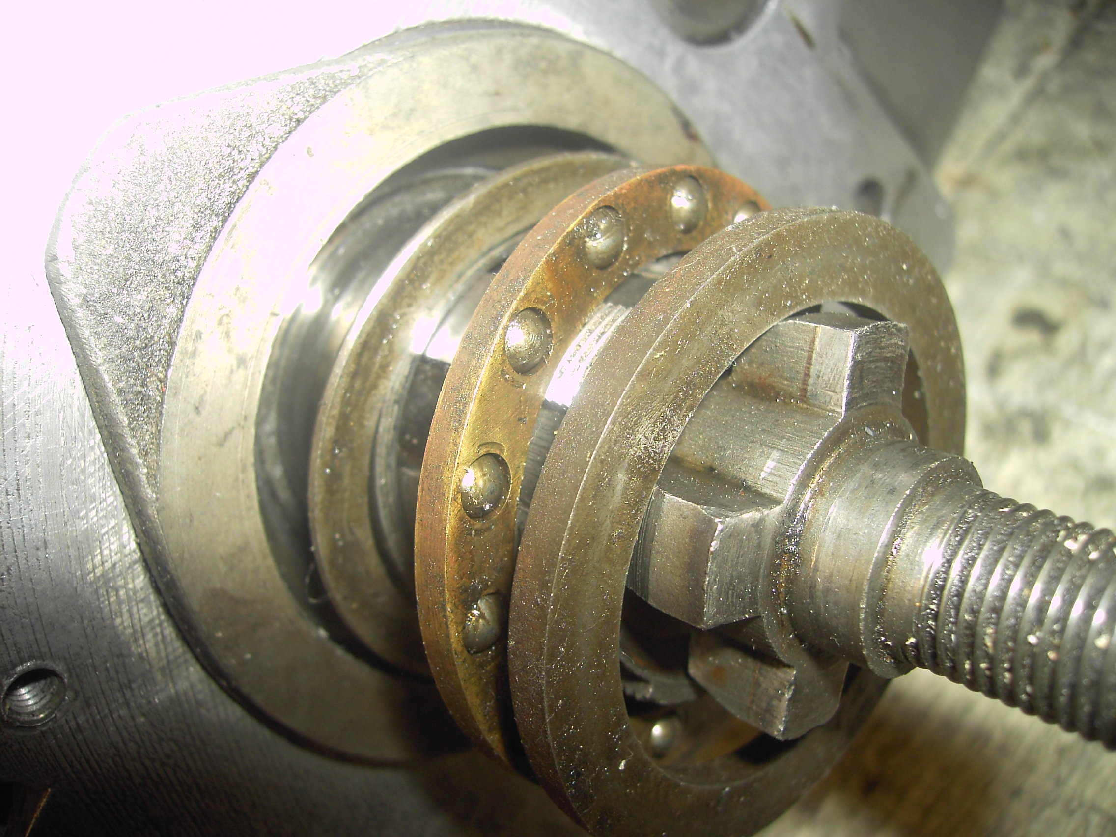
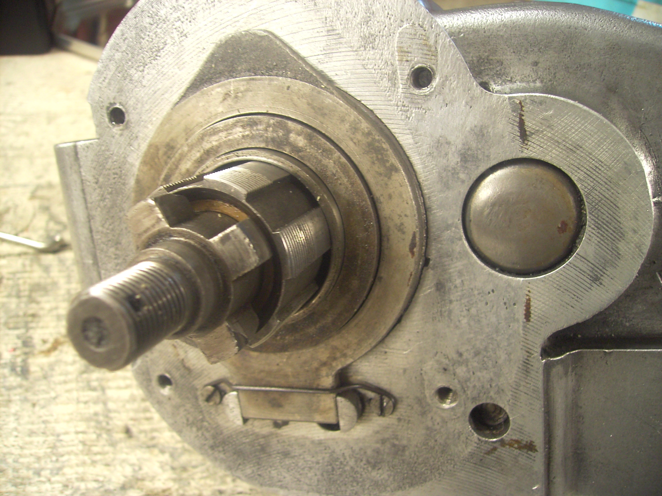
Gearbox
Dismantled with no problems and will polish casing with my buffing wheels attached to grind wheel


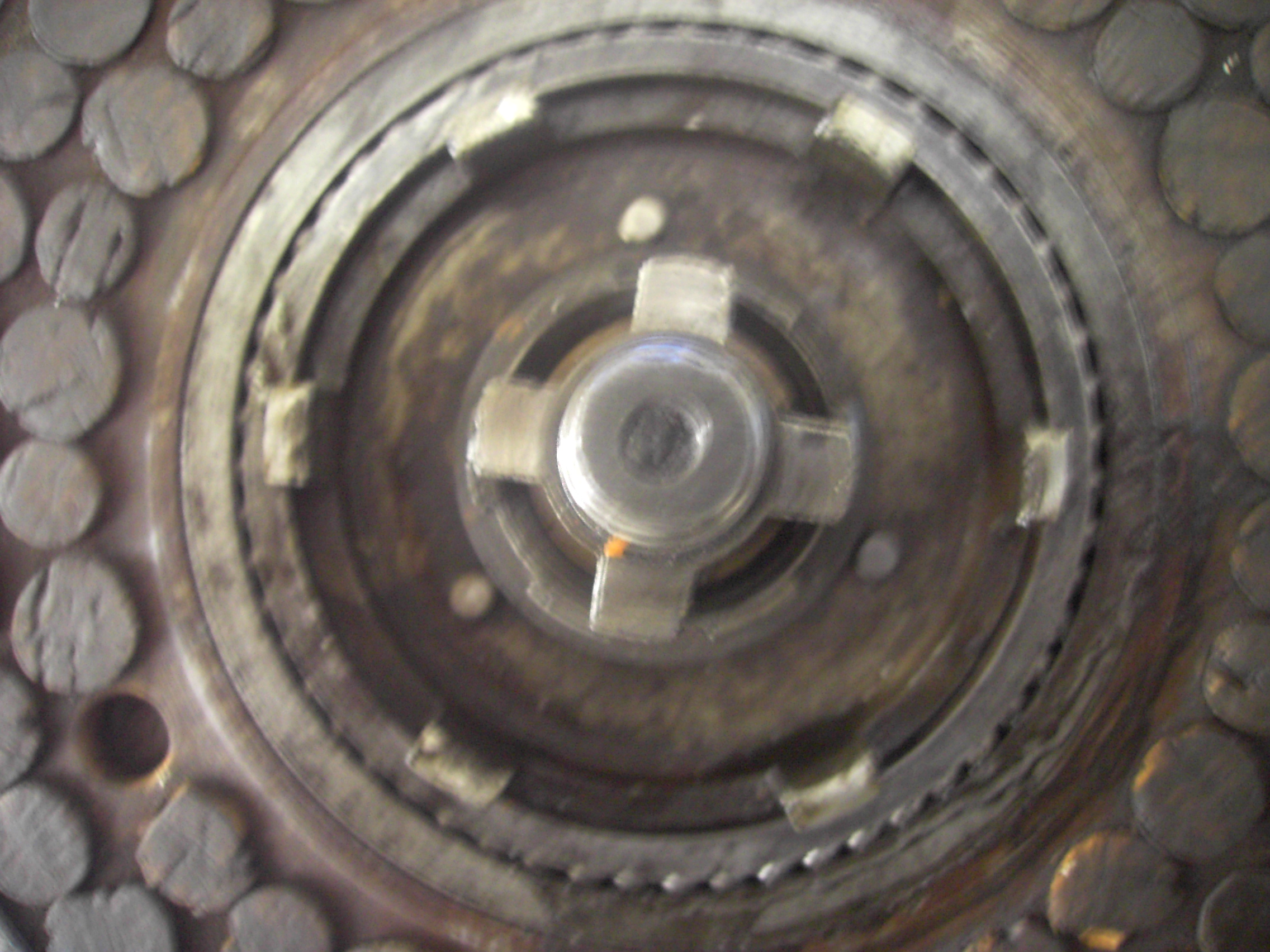
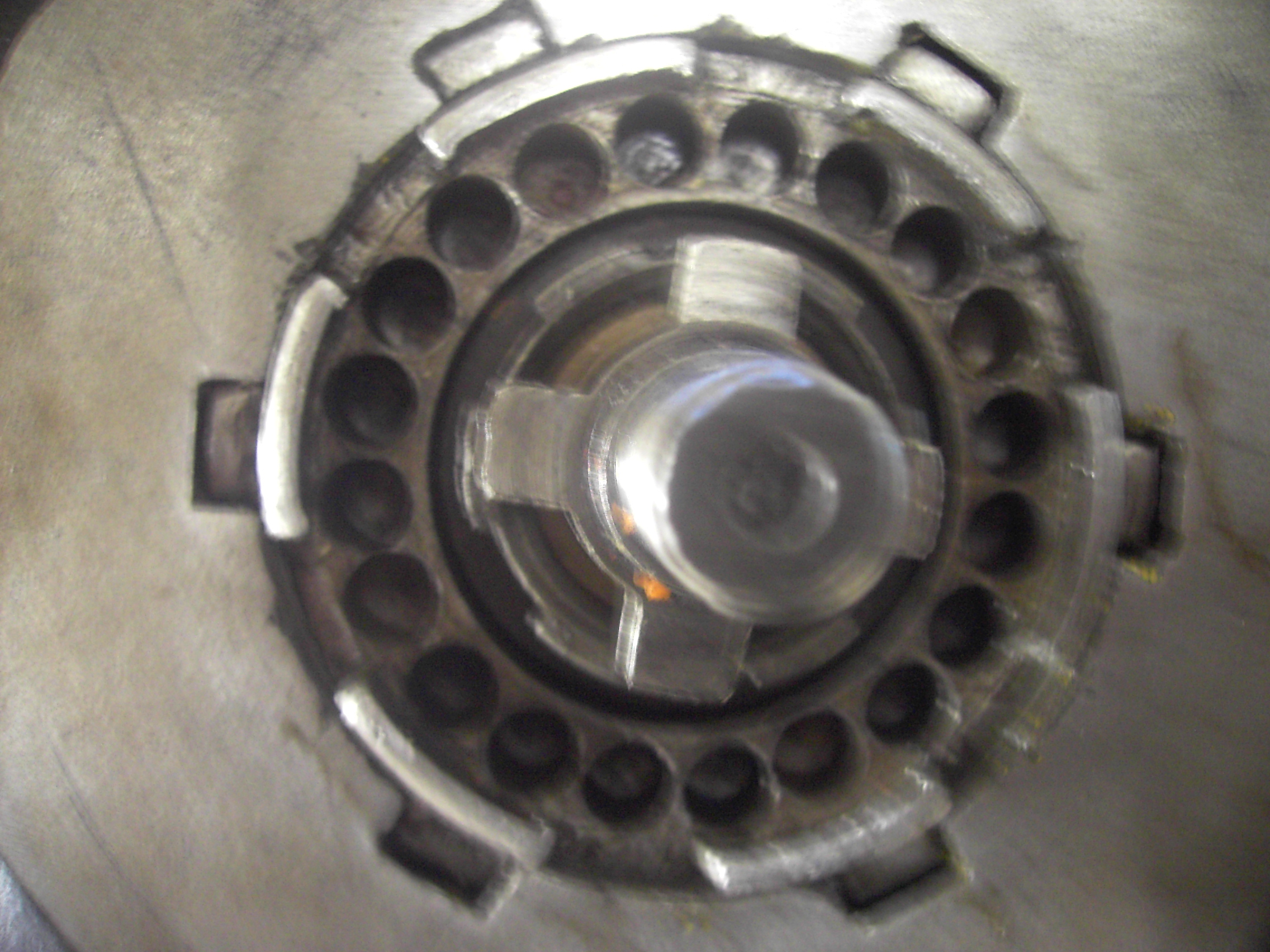
Clutch
Assembled one plate clutch great care is required with spring insertion
Brackets fitted OK and I have made the mounting bolts I purchased 2metres of 3/8 inch mild steel rod and also various size BSCYl taps and dies
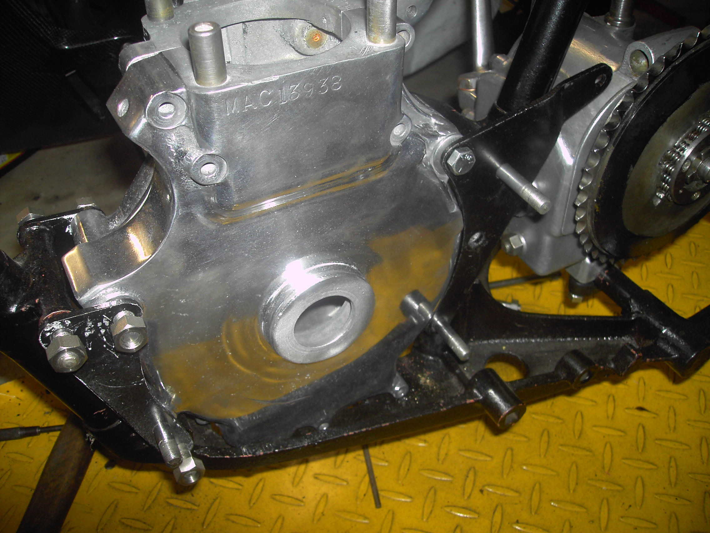
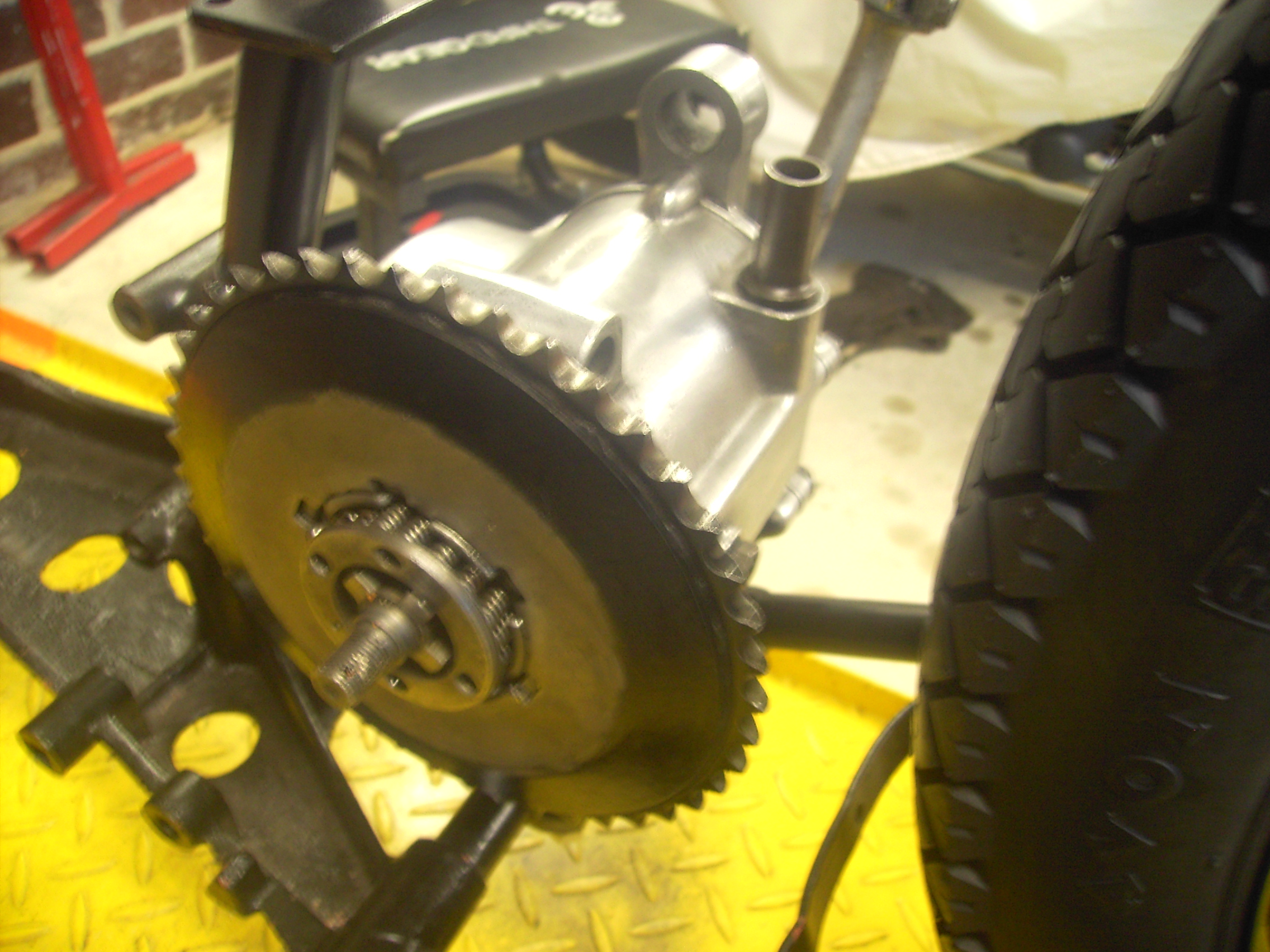
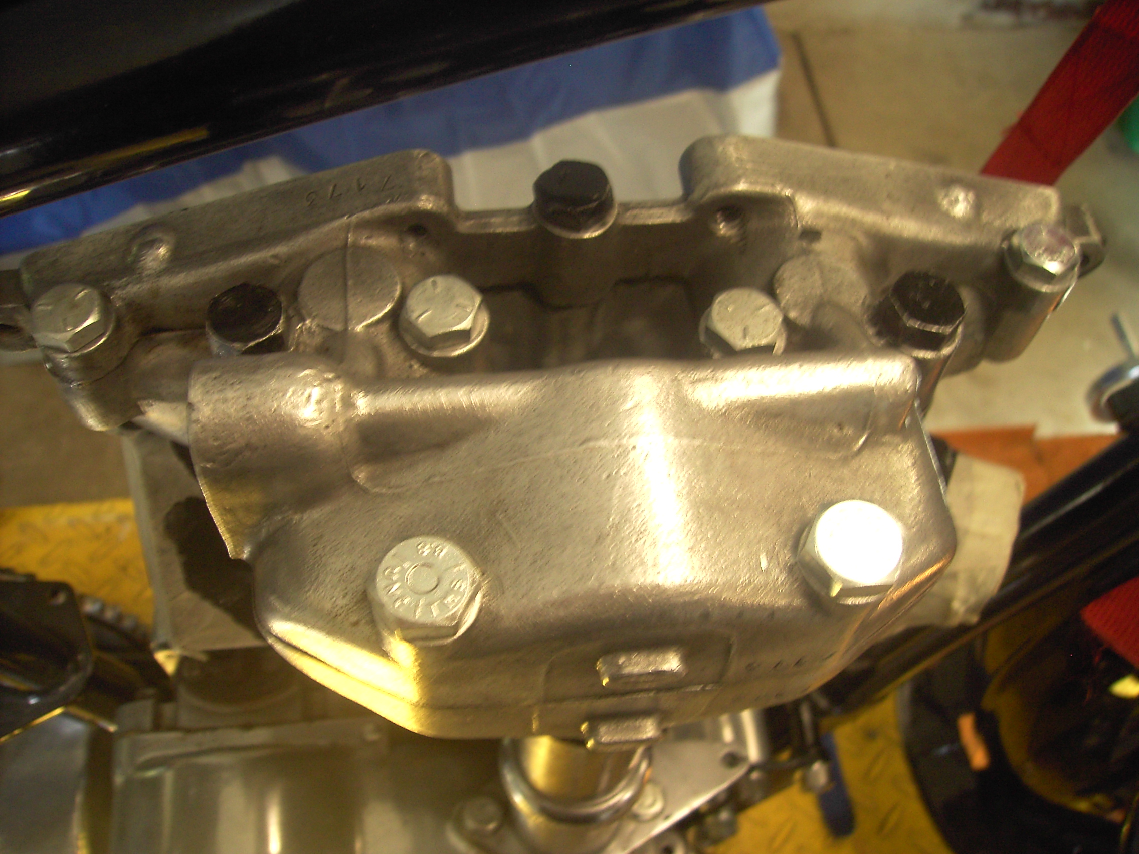
Engine
This has been a real challenge as the engine was far from complete but I have completed the following and awaiting a die 2ba so i can make a puller for the timing gear drive gear
- purchased 40thou oversized rings and piston after bore machined
- Purchased timing gears
- Purchased cam followers and rods
- Purchased magneto and auto advanced gear assembly
- Had crankcase components metal polished
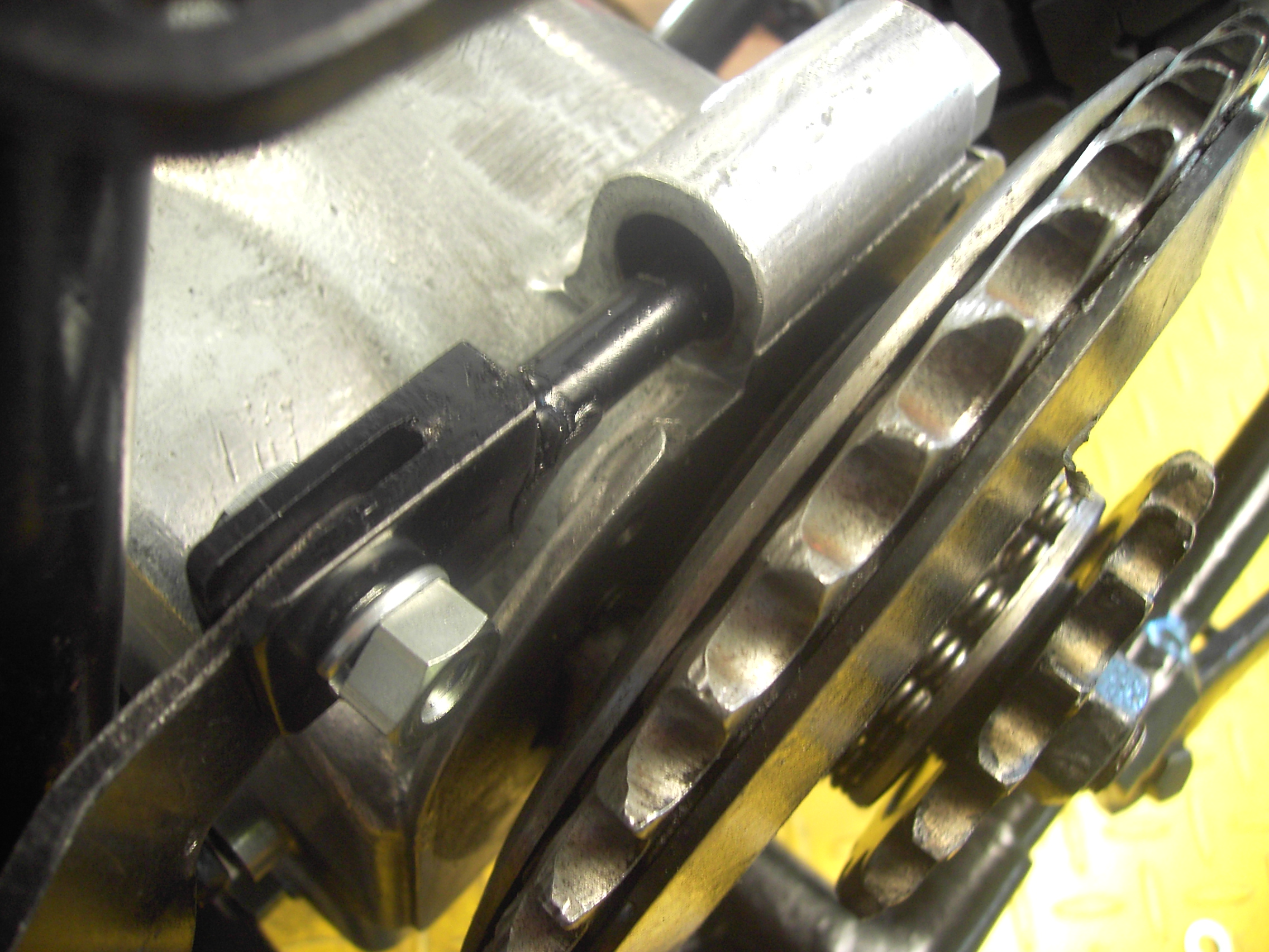
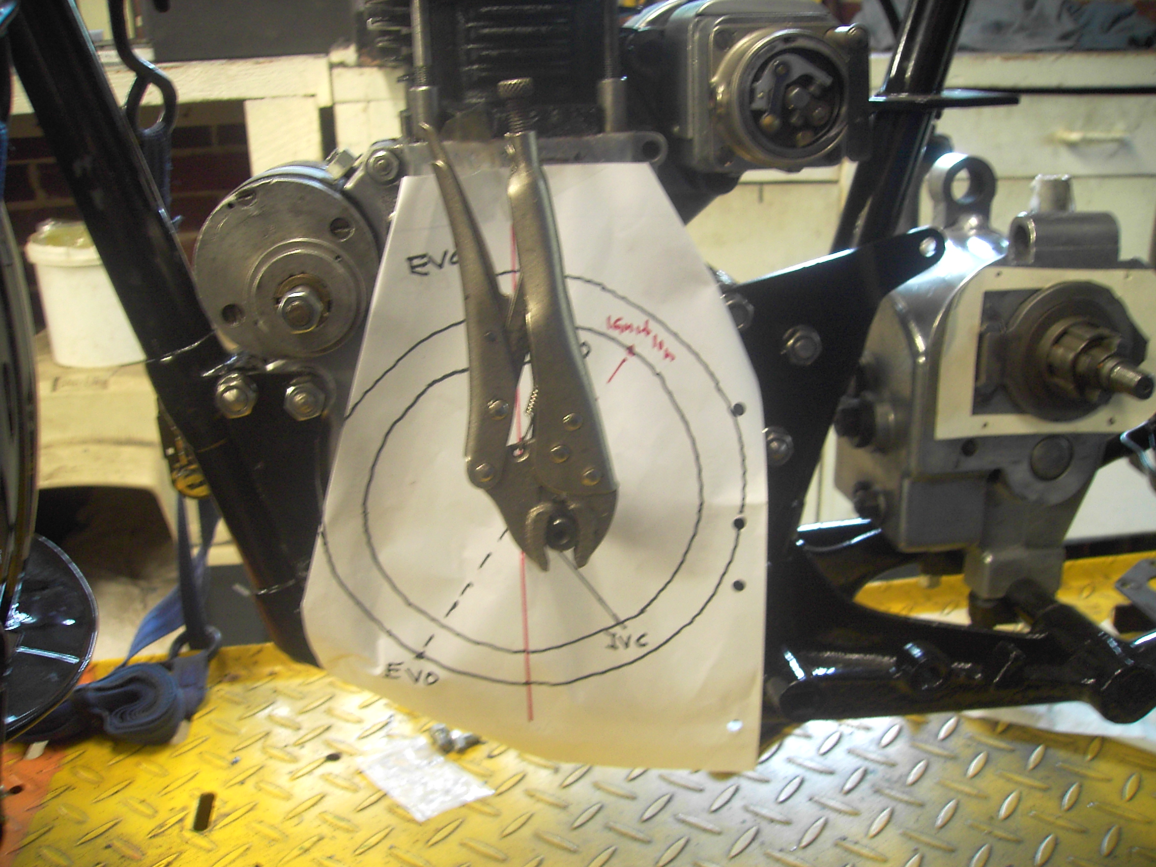
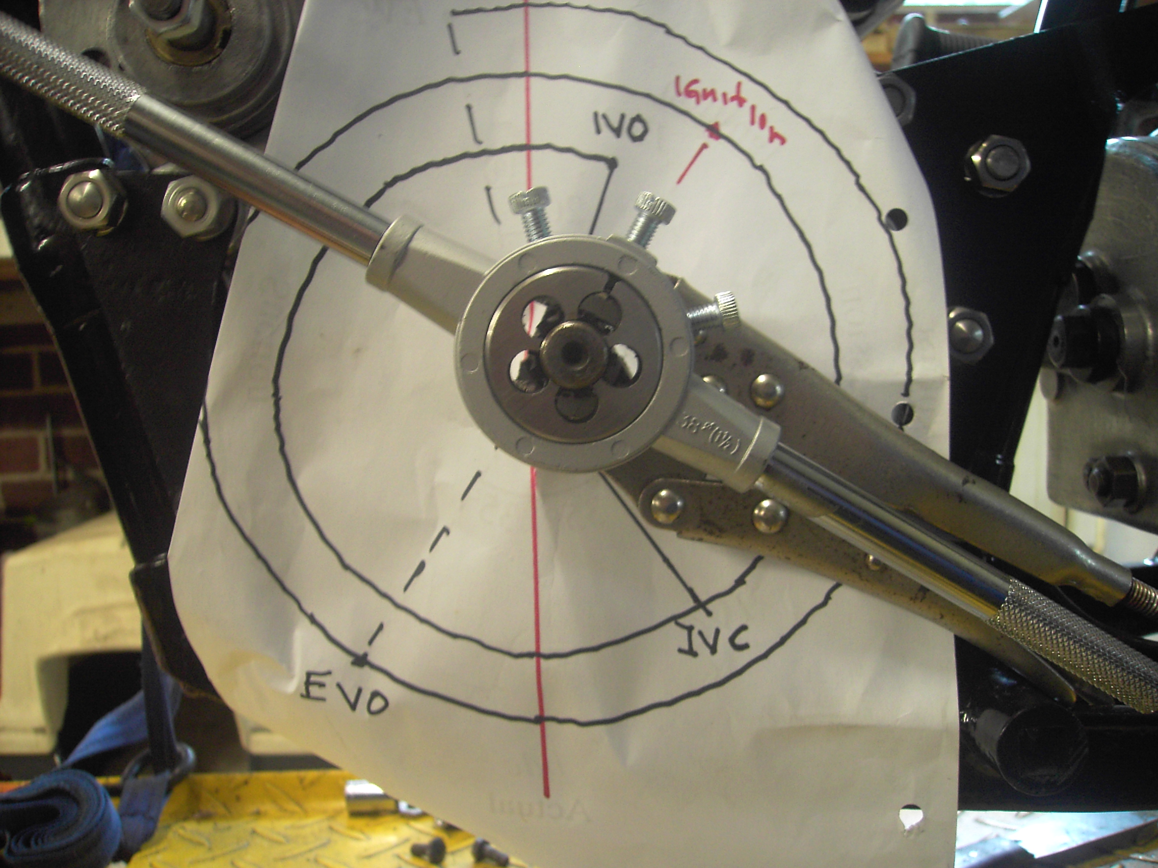
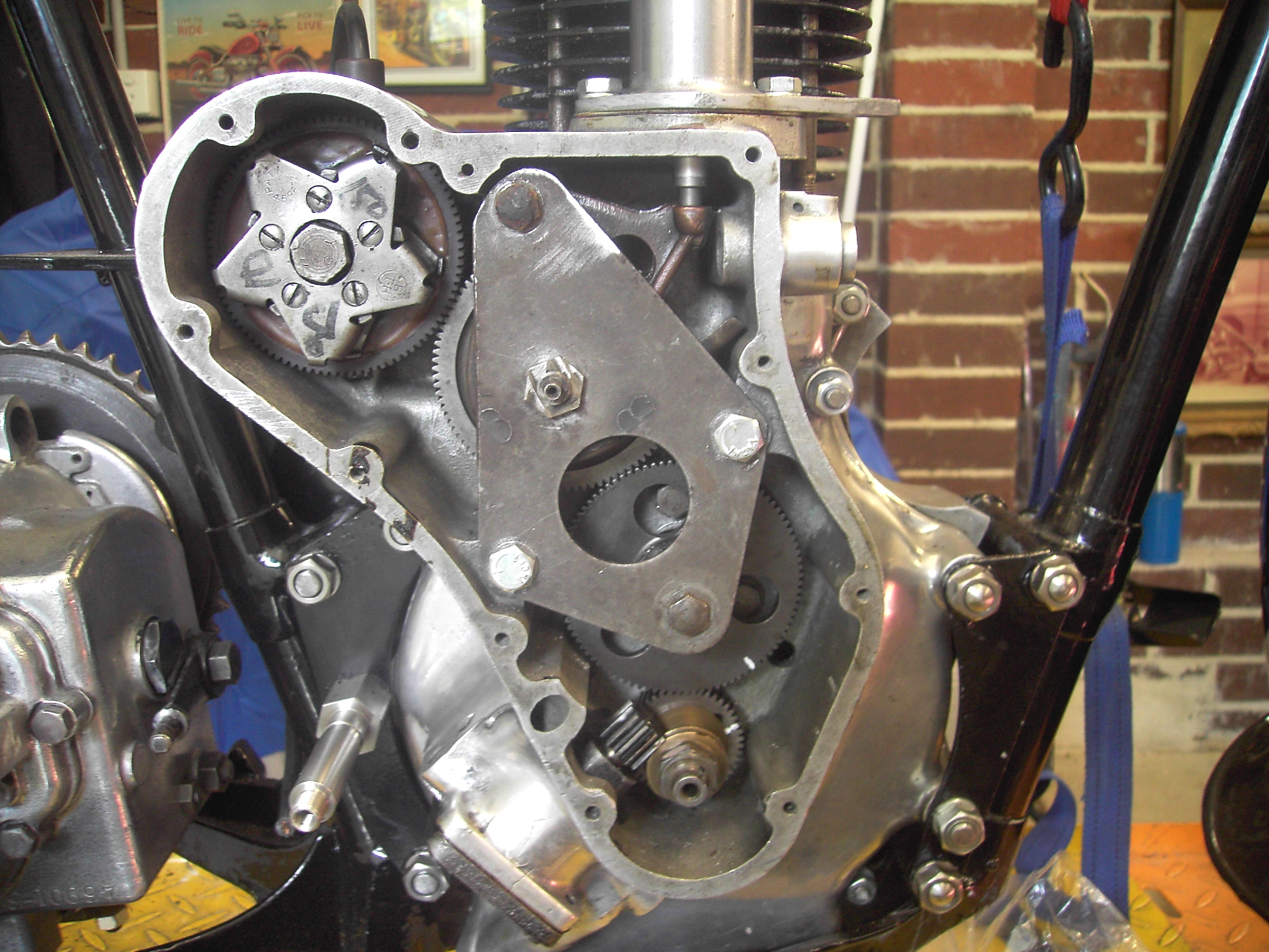
Manufactured puller to remove main crank gear then commenced timing, as I have sourced all components from different locations and suppliers in other words gears came from different sources I decided to time from first principles with assistance from my son.
To do this I made a circle diagram template and meshed gears to achieve the correct cam timing, then obviously did the ignition timing.
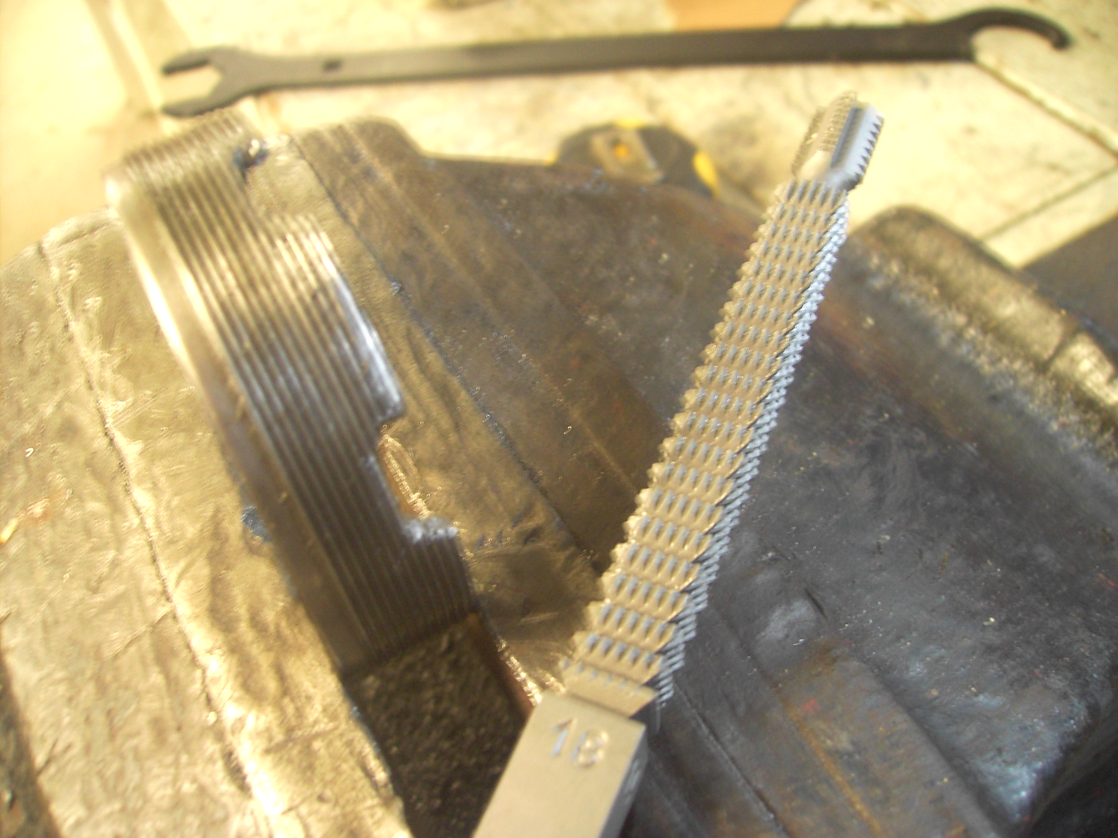
I also had to buy a die to clean up crankshaft thread also a thread file for engine clutch
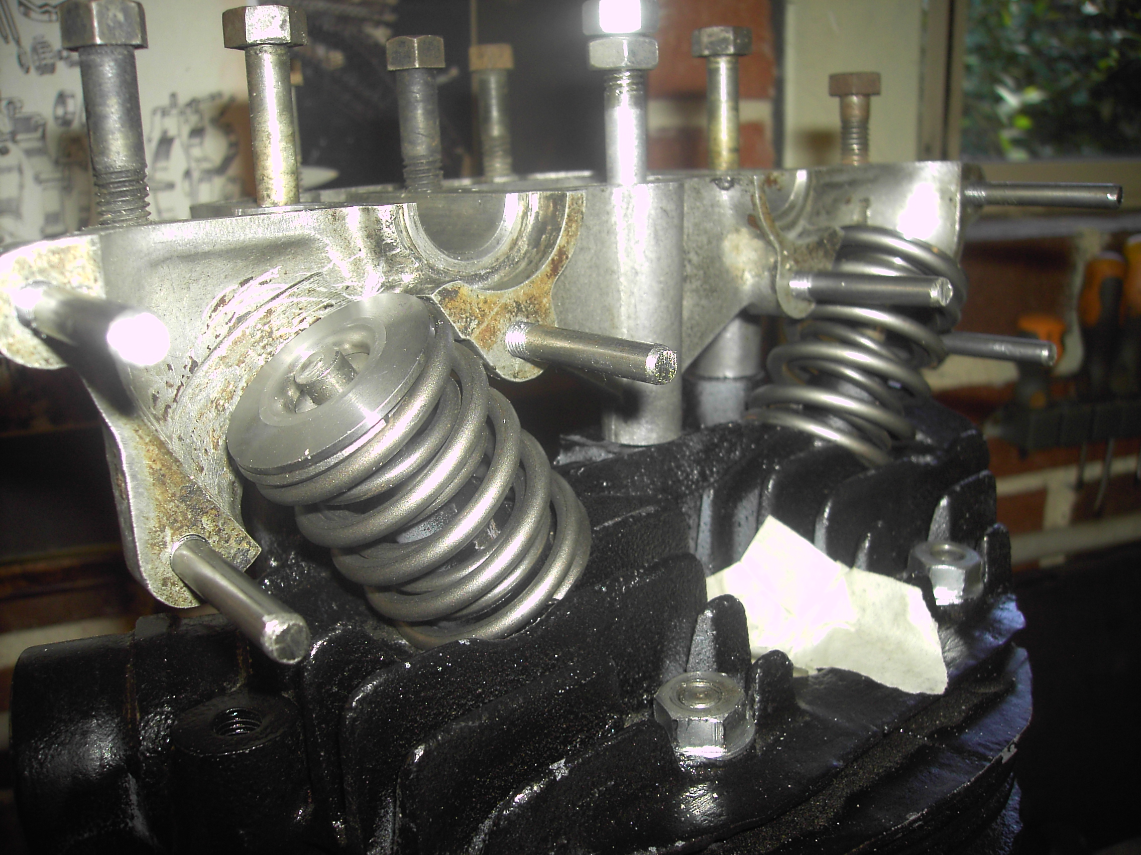
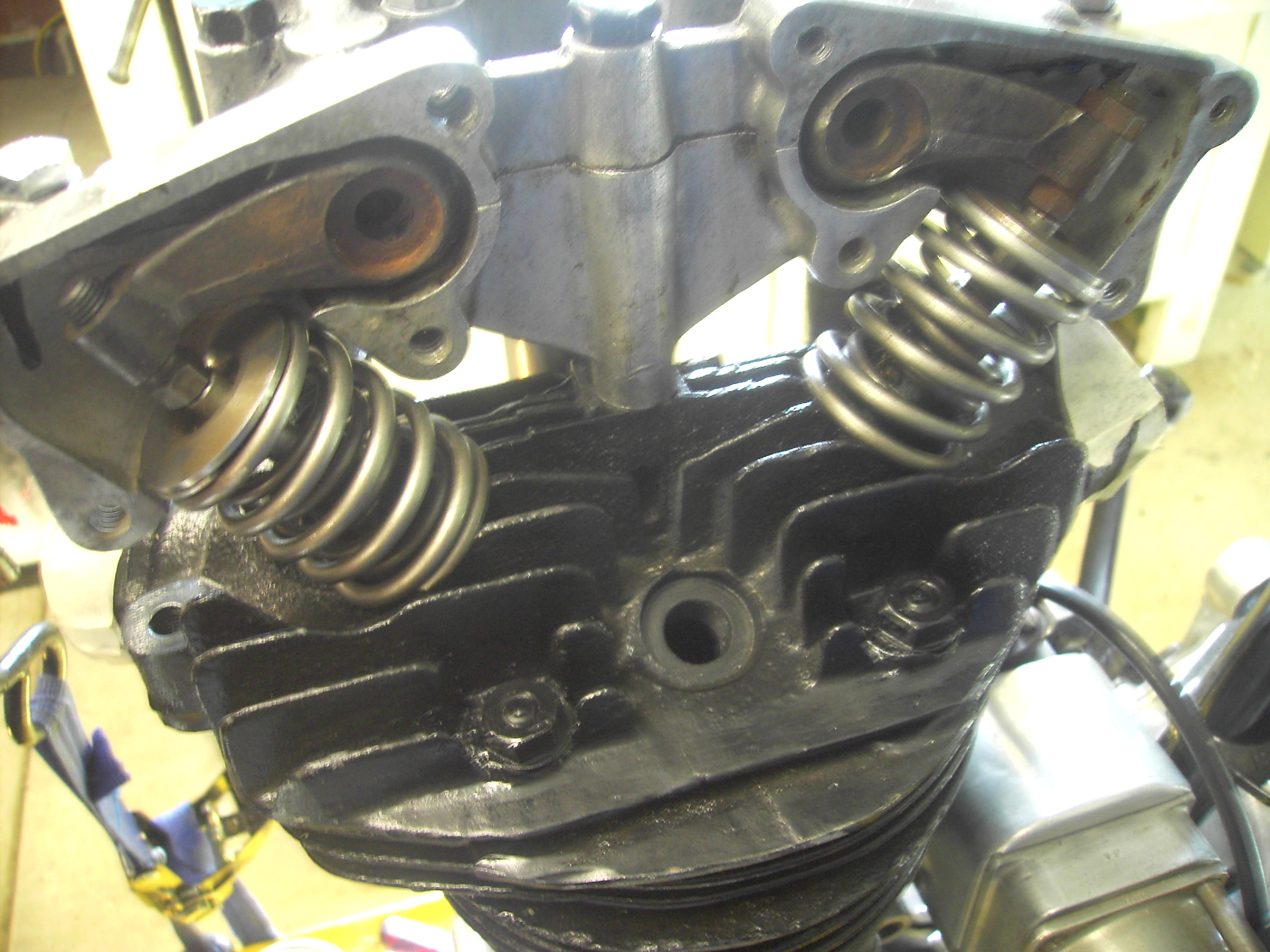
Tappett clearances adjusted ready to close up
Final Assembly
Well as I draw near to completion I have compiled some photos marking the progress and I will then begin the wiring as a separate issue

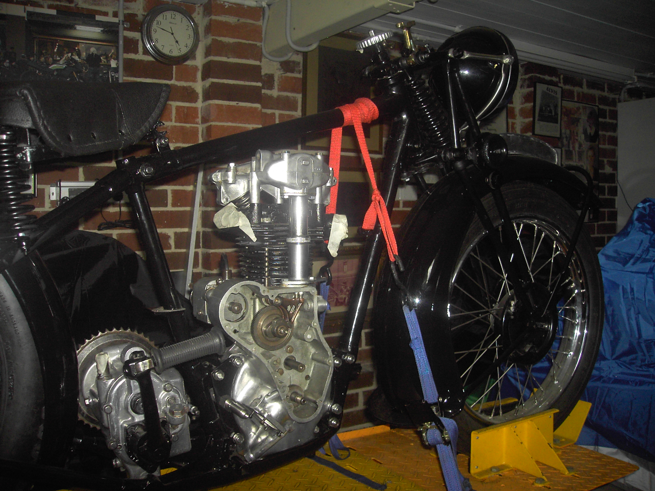
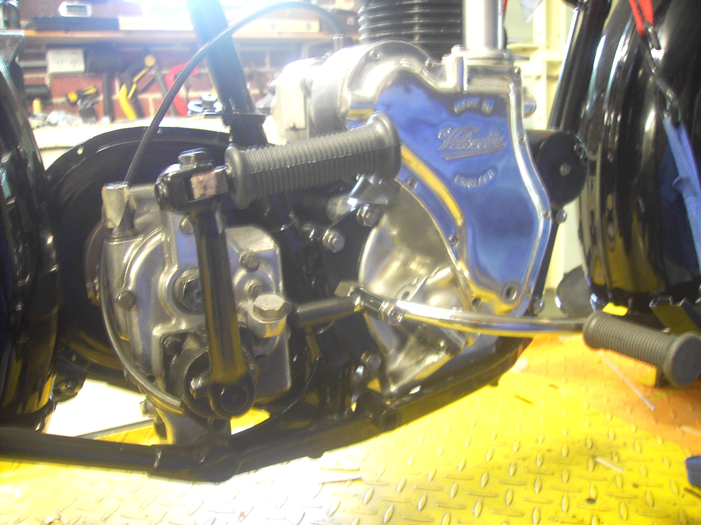
[gallery ids="1354,1355" type="rectangular"]
[gallery ids="1357,1358,1360,1361" type="rectangular"]
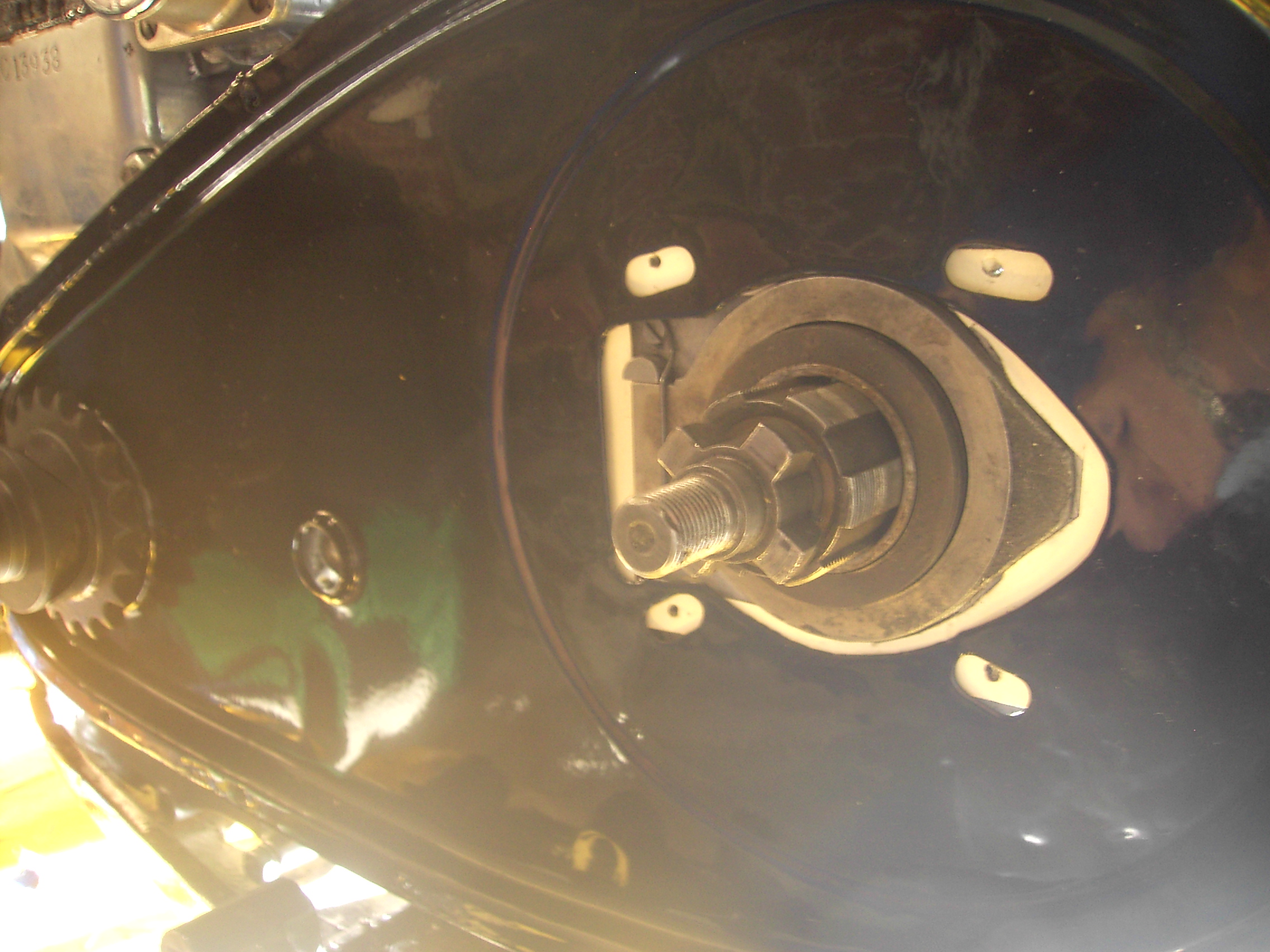
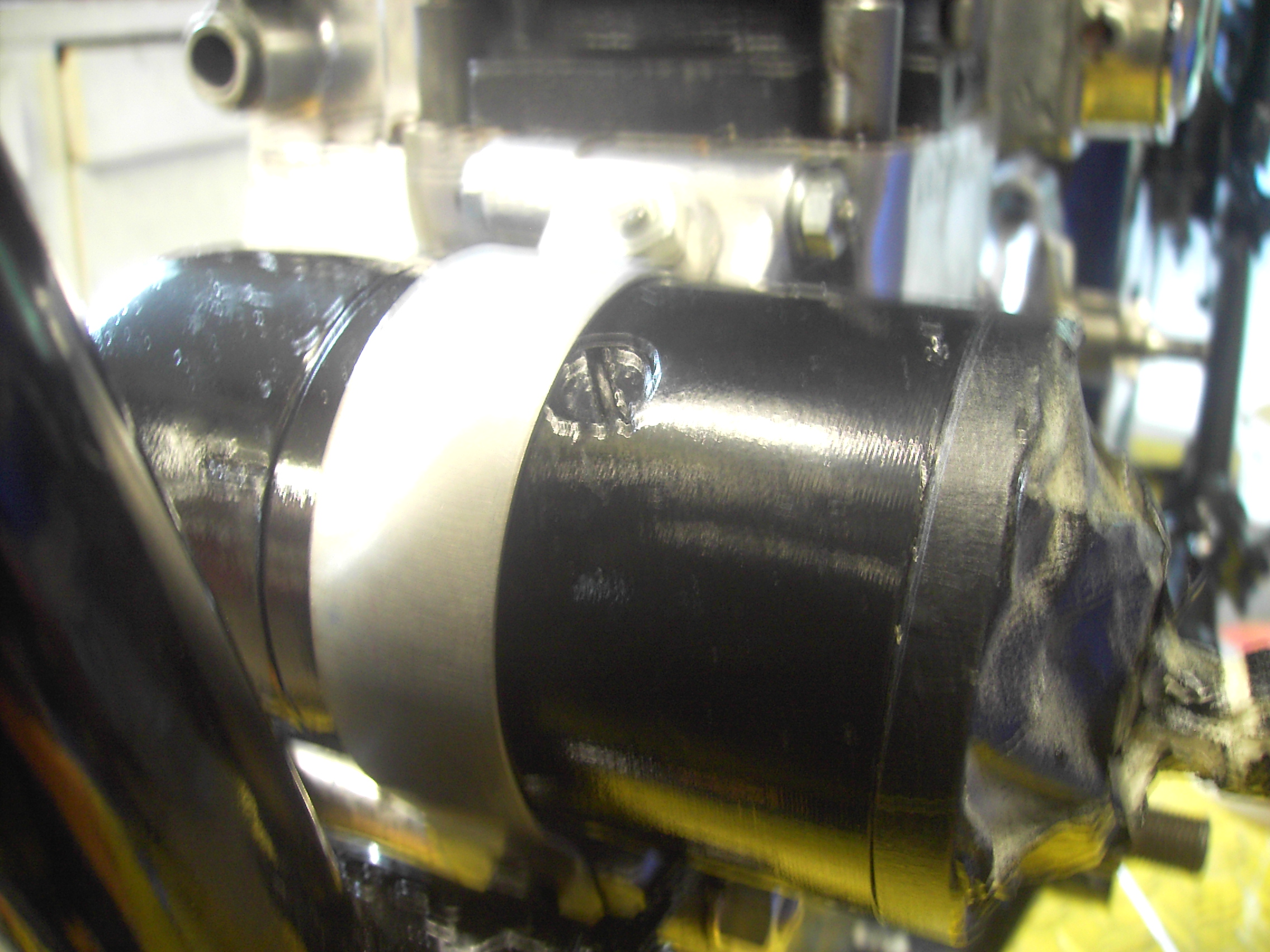
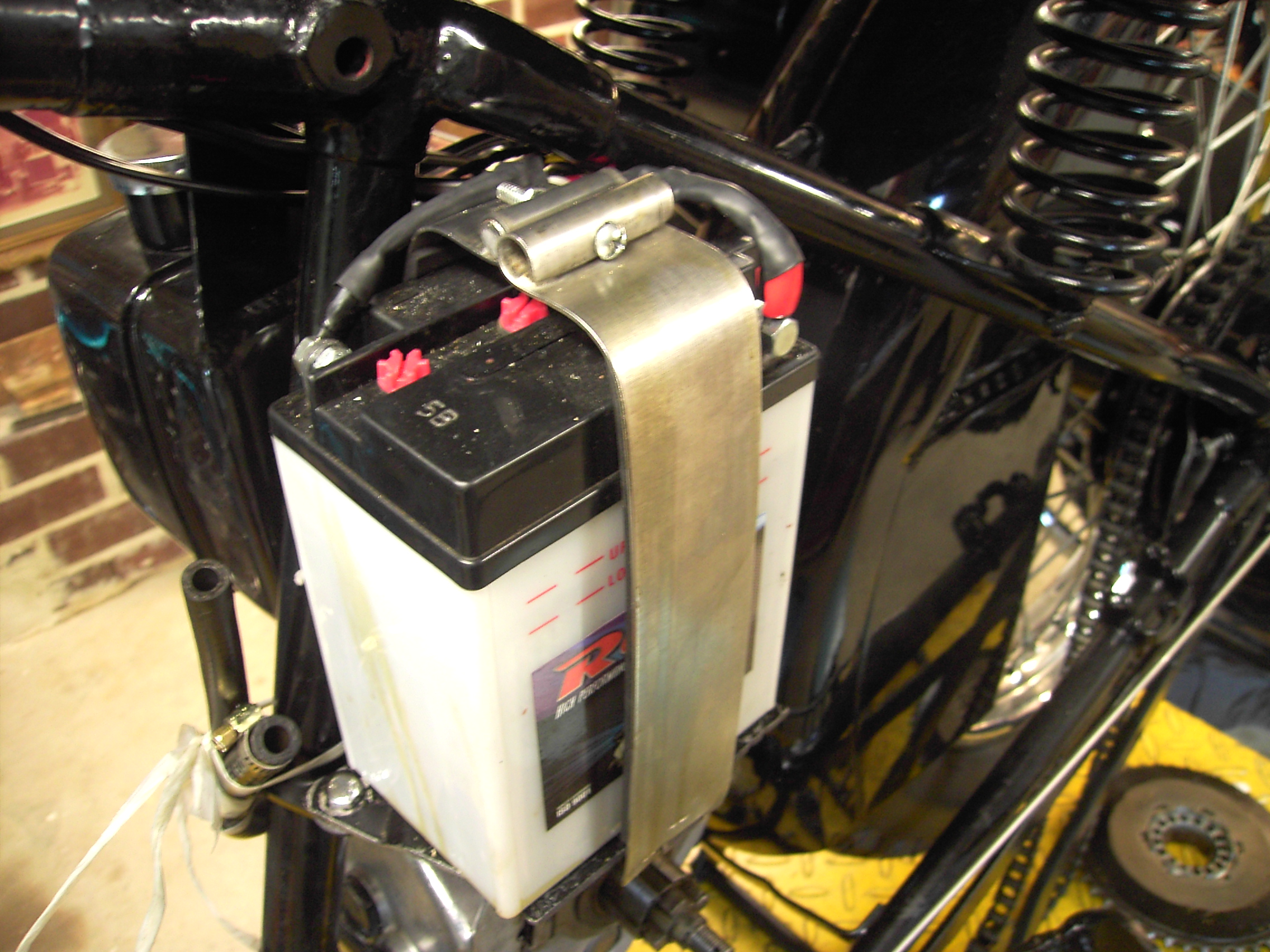
Dynamo regulator mounted, battery straps made, and carburettor fitted
[gallery ids="1359,1363,1362" type="rectangular"]
Manufactured oil pipe for valve chamber
[gallery ids="1365,1366" type="rectangular"]
I was able to persuade my son Paul to carry out the wiring for me and did an excellent job There was the need to use some initiative in fixing the light switch to ensure it was secure in the head light nacelle. Horn was also fitted and wired together with horn button.
[gallery ids="1377,1378" type="rectangular"]
Battery inserted to test all wiring worked perfectly
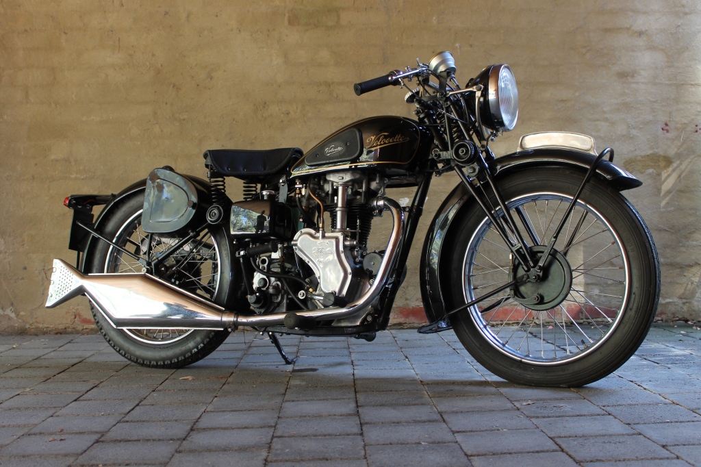
 Ready to run see photos below before the big test
[wpvideo 1DJcpPBL]
Success runs really well


Bikes look amazing cuz. Will have to come out for a squiz..
ReplyDeleteThanks Jeff that would be great
ReplyDeleteemail is matt.crosbie@activ8.net.au